Optical Chopper System
18488-D02 Rev G, September 24, 2012 Page 23 www.thorlabs.com
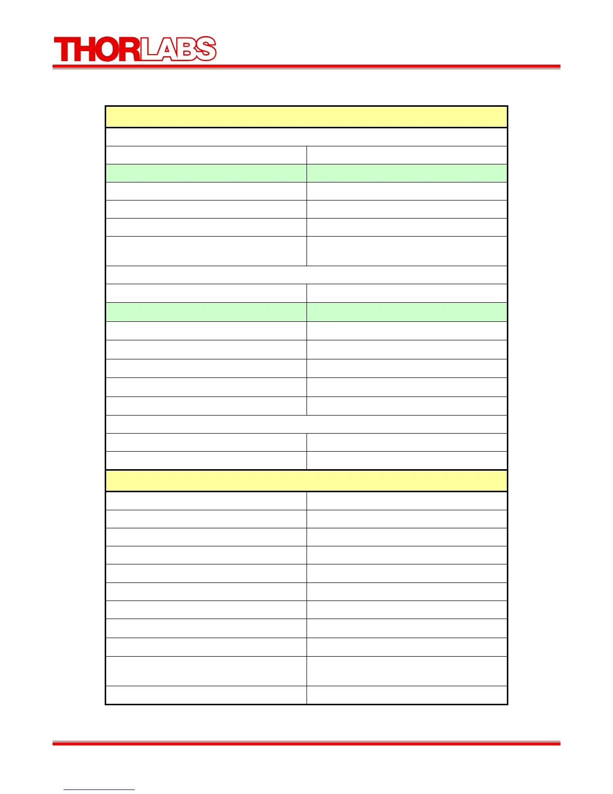
Part 10. Specifications
Performance Specifications
Chopping Frequency
MC1F2 (2 slot) 1 – 99 Hz
MC1F10 (10 slot, Default Blade) 20 – 1 kHz
MC1F15 (15 slot) 30 – 1.5 kHz
MC1F30 (30 slot) 60 – 3 kHz
MC1F60 (60 slot) 120 – 6 kHz
MC2F57 (2f slot) Outer: 14 – 700 Hz
Inner: 10 – 500 Hz
Phase Jitter (@ max freq)
MC1F2 (2 slot)
0.05° rms Max
MC1F10 (10 slot, Default Blade)
0.42° rms (0.13° rms Typ.)
MC1F15 (15 slot)
0.68° rms (0.27° rms Typ.)
MC1F30 (30 slot)
1.10° rms (0.45° rms Typ.)
MC1F60 (60 slot)
1.10° rms (0.78° rms Typ.)
MC2F57 (2f slot)
0.38° rms (0.08° rms Typ.)
Frequency Drift
<20 ppm/°C
Chopping Range
Harmonic 2 to 15x
Sub-Harmonic 1/2 to 1/15x
Input/Output Specifications
Ext. Input Compatibility TTL/CMOS
Ext. Input Voltage Range
(2)
0 – 5 V
Input High >2 V
Input Low <0.8 V
Ext. Input Impedance
200Ω
Ref Out Compatibility TTL/CMOS
Ref Out Voltage Range
(2)
0 – 5 V Typ.
Ref Out Impedance
200Ω
Min Load Impedance
(3)
500Ω
Ref Out Signals Inner/Outer Slot Chopping Blade, Synthesizer,
Sum and Diff Frequencies
Ref Out Selection Selectable Menu or USB command ‘O ’