Optical Chopper System
18488-D02 Rev G, September 24, 2012 Page 8 www.thorlabs.com
Part 3. Setup
1. Carefully unpack the MC2000 controller, optical head, and accessories. See below for a
complete list of parts. If any of the items appear damaged or missing, do not use the MC2000.
Call Thorlabs, or email RMA@thorlabs.com and arrange for a replacement.
Parts List:
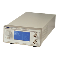
• MC2000 Control Box
• MC2000 Optical Chopping Head
• MC1F10: 10-slot chopping blade
• 2 meter mini circular cable for optical head / control box interface
• This Operating Manual
• Power Supply Line Cord: 120 VAC with the MC2000 or 230 VAC with the MC2000-EC
• 125 mA Fuse for use at 230 VAC operation (250 mA fuse installed in unit)
• 1/16" Allen Key for blade replacement
• 0.05" Allen Key for hub alignment.
• (3X) 4-40 x 1/8" Phillips Pan Head Screws with Internal Tooth Washers
2. Remove the 3 mounting screws and lock washers from the chopper blade hub using the 1/16"
hex key provided.
3. Unpack the 10-slot blade and install onto chopper blade hub using the 3 screws and washers
removed in the previous step. Tighten the screws securely with the hex wrench.
4. Attach the modular cord into the circular connector labeled ‘OPTICAL HEAD’ on the back of
the MC2000 controller and plug the other end into the circular connector on the optical head.
5. Mount the optical head on a sturdy surface in an area free of obstructions. Make sure the blade
can spin freely.
6. Attach the AC line cord to the MC2000 and plug into an AC outlet.
Note: the MC2000 can be operated from 100/115 VAC or 230 VAC. A voltage selector switch is located
inside of the MC2000 controller. If you are not sure what operating voltage your unit is set to, proceed
immediately to Part 8. Fuse Replacement and Line Voltage Selection on page 20 for instructions on
setting the operating voltage.