Page 8
MTN003813_D02
PDB2xx Series
3 Operating Instructions
3.7 CMRR and Frequency Response
An important specification for balanced amplifiers is the Common Mode Rejection Ratio
(CMRR) that reflects the ability to suppress common mode noise.
In the setup described below, the Device under Test (DuT) - here a PDB2xx Series balanced
detector - is tested for CMRR. A common mode signal is generated, which is canceled out
when the amplifier is in balanced mode.
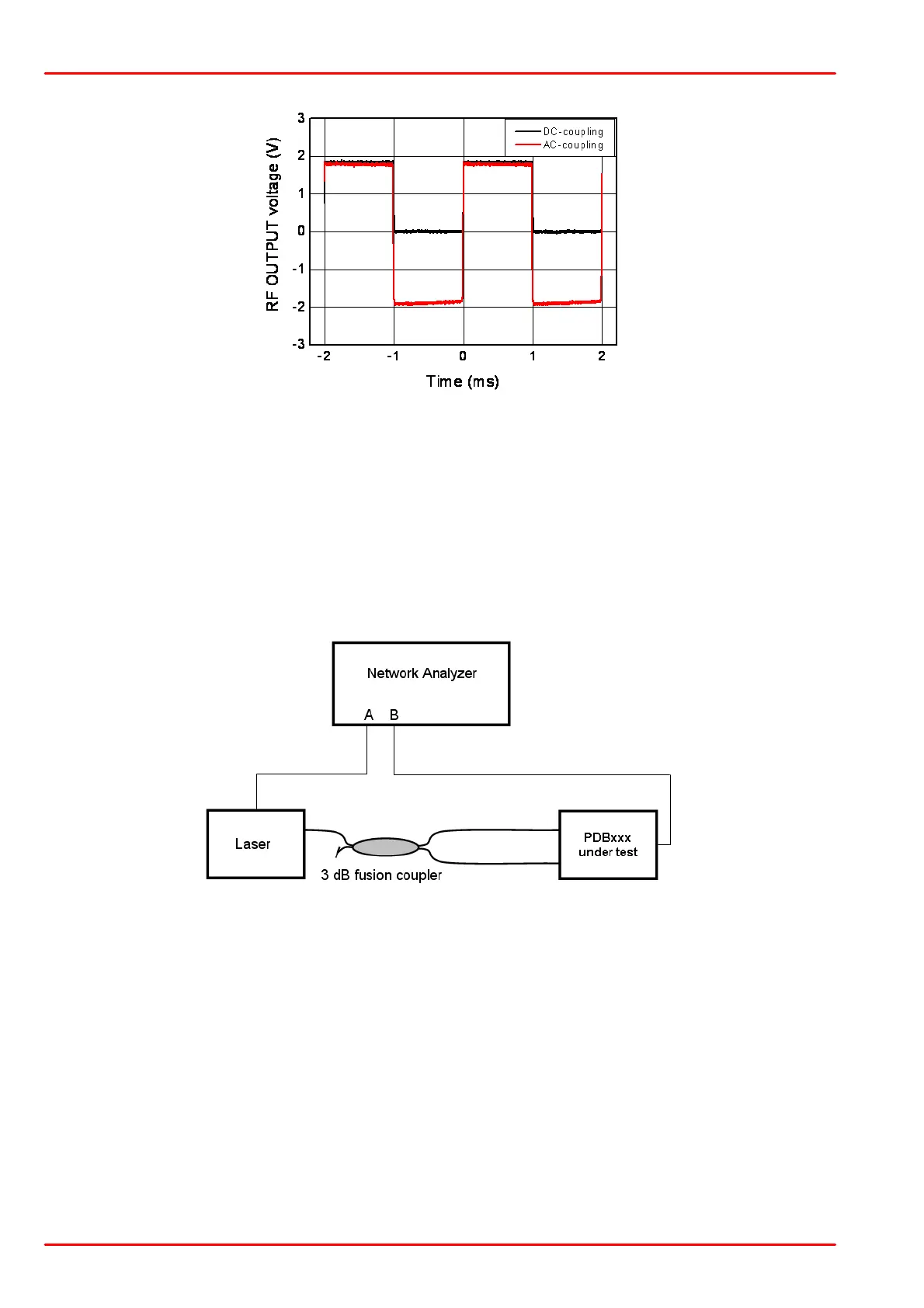
A network analyzer is used as signal generator (output A) and receiver (input B) The receiver is
synchronized with the signal generator and measures selectively at the same frequency. A
laser light source is modulated by the signal generator (port A) and acts as transmitter. A 3 dB
fusion coupler is connected to the laser output, splitting the modulated light signal into two
paths. Depending on the measurement task, one or both coupler outputs are connected to the
input ports of the DuT. One of the DuT output ports is connected to the network analyzer Port
B.
Frequency Response Measurements
The frequency response of each signal path can be measured by connecting only one coupler
output to the appropriate input. In this way, the frequency response curves of the RF OUTPUT
from INPUT+ and INPUT- can be measured, as well as the frequency responses of the
MONITOR output ports, as shown in the individual technical data.
CMRR Measurement