Rev: 2.4, 16-Jul-2021 © 2021 Thorlabs Page 5
3 Operating Instructions
PDB2xx Series
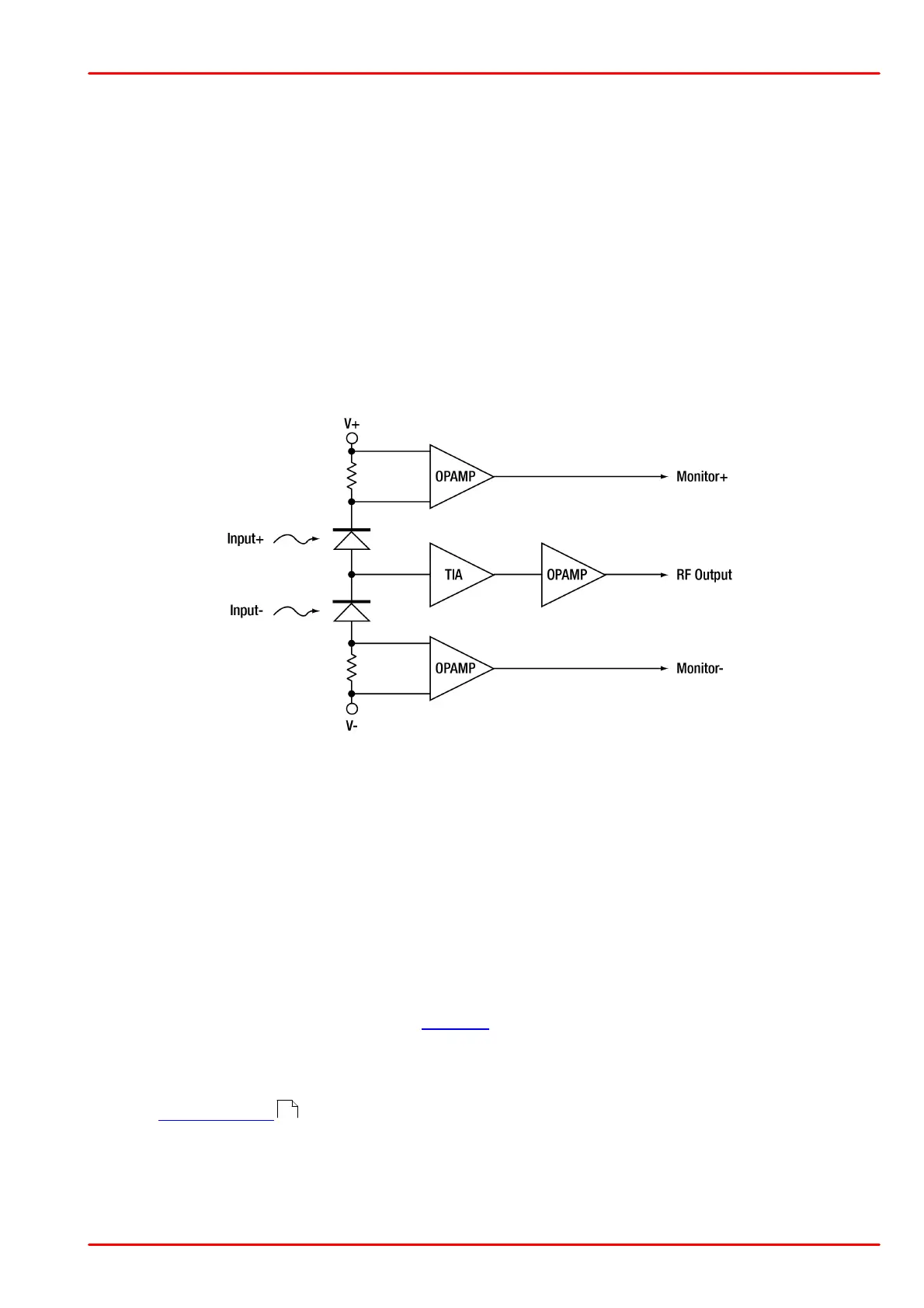
3.2 Operating Principle
Thorlabs PDB2xx Series Balanced Amplified Photodetectors consist of two well-matched pho-
todiodes and an ultra-low noise, high-speed transimpedance amplifier that generates an output
voltage (RF OUTPUT) proportional to the difference between the photo currents of the two pho-
todiodes, i.e. the difference of between the two optical input signals.
Additionally, the unit has two monitor outputs (MONITOR+ and MONITOR-) to observe the op-
tical input power level on each photodiode separately. Due to the increased cut-off frequency,
the output from Monitor+ and Monitor- can also be used to measure low frequency modulated
signals on each detector separately.
The PDB2xx Series is powered by an external linear power supply (included; ±12 V, 250 mA)
via a PICO M8 power connector.
Below is a functional block diagram of the PDB2xx Series Balanced Amplified Photodetectors:
3.3 Optical Input
The PDB2xx Series detectors have two free-space optical input ports. Open beams should be
carefully aligned to both detectors. This is particularly critical for PDB230A and PDB230C,
which have a smaller photodiode active area. When working with large beam diameters, addi-
tional focusing lenses can be placed in front of the optical inputs to avoid overfilling the active
detector area. For this, Thorlabs offers a large variety of lenses and mounting accessories. The
housing is compatible with any number of Thorlabs SM1- and SM05-threaded accessories, al-
lowing for easy integration with external optics, filters, apertures, or fibers adapters as well as
Thorlabs cage assembly accessories.
For fiber coupled applications, Thorlabs S120-xx series fiber adapters can be easily mounted to
the optical input ports. Thorlabs offers such adapters for single-mode fibers (connector styles
FC, SC, ST and LC) and for multi-mode fibers (connector SMA).
The RF OUTPUT will saturate at an optical input power greater than the CW Saturation Power
listed in Specifications . If necessary, use external neutral density filters or attenuators to re-
duce the input light level. Please note, that the PDB2xx Series Balanced Amplified Photodetect-
ors are very sensitive to unwanted stray light. It is important to carefully shield the input aper-
tures from any unwanted light sources. Common techniques include the use of baffling or other
opaque barriers, such as black cloth or lens tubes, and placing appropriate band pass filters in
front of the detector to minimize the influence of stray light.
12