© 2019 Thorlabs
3 Operating Instructions
12
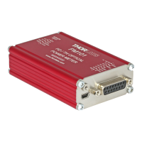
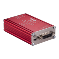
3.2.6 USB Operation
All PM101x models can be run via the USB port.
The USB interface on all PM101x models also serves to connect the power meter to a power
supply and to update firmware of the PM101x.
The PM101U uses the USB interface as the only port for control and output.
Note
In case a USB communication is established in addition to the DA-15/DE-9 connection, PM101
and PM101R switch to USB-Mode and the DA-15/DE-9 serial interface becomes inactive. Only
after actively closing the USB connection, the serial communication is reestablished.
When switching the PM101 or PM101R from USB to RS232 operation or, in the case of
PM101, to UART operation, PM101R and PM101 use the DA-15 or DE-9 interface for control
and output.
3.2.7 RS232 Operation
The power meters PM101 and PM101R can be operated with serial communication via
RS232.
Please use a RS232 standard protocol for RS232 communications. For questions, please con-
tact our engineers at Thorlabs .
Please set up the port as follows:
115.200 Bit/s (default)
Supported range of Baud Rate: 9.600 and 230400 Bit/s
LF (x0A; \n). The termination character needs to be enabled.
Note
PM101:
To operate the PM101 via RS232, RxD, TxD, and GND need to be wired from the DA-15 con-
nector to a 9 Pin female connector to perform the connections.
25