© 2019 Thorlabs
4 Appendix
20
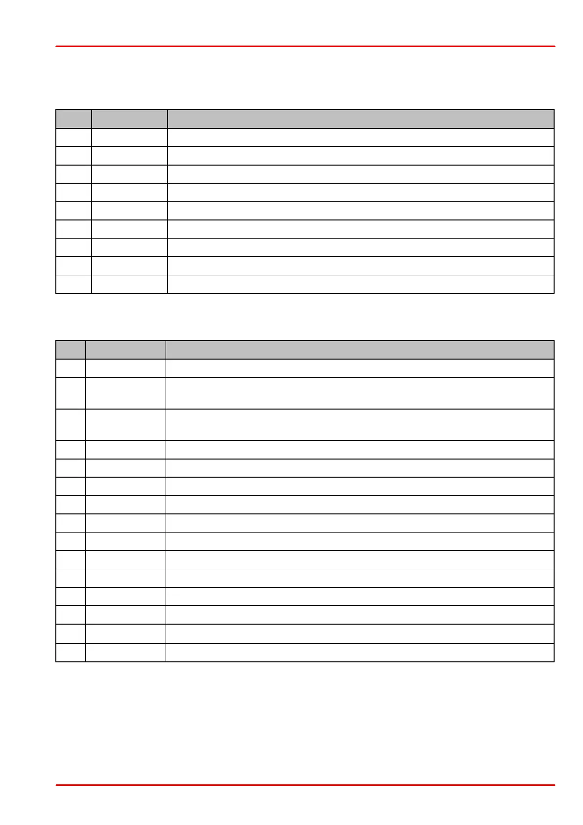
4.2 Pin Assignment Output Connector
PM101R: PM101R has a serial DE-9 connector. The Pins are assigned as follows:
RS232: Connect to PC Terminal RxD (PC DE-9 Pin2)
RS232: Connect to PC Terminal TxD (PC DE-9 Pin3)
RS232 Signal Ground: Connect to PC Terminal Ground (PC DE-9 Pin5)
PM101: PM101 has a universal DA-15 connector. The Pins are assigned as follows:
Pin for Alternative Power Supply with 5 VDC to 36 VDC
General Digital Input / Output port; 3 V logic (Output), 5 V tolerant for In-
put
General Digital Input / Output port; 3 V logic (Output), 5 V tolerant for In-
put
Analog Output; -0.25 V to +2.5 V per Measurement Range
Software Configurable Analog Output; 0 V to 2.5 V
RS232; Connect to PC terminal RxD (PC DE-9 Pin2)
RS232; Connect to PC terminal TxD (PC DE-9 Pin3)
NTC Thermistor Input; Measurement Range 0.1 kW to 100 kW
RS232 Signal Ground; Connect to PC Terminal Ground (PC DE-9 Pin5)