EasyManua.ls Logo

Thule BSTK2 User Manual

Thule BSTK2
6 pages
To Next Page IconTo Next Page
Page #1 background imageLoading...
Page #1 background image
BSTK2 BIKE STACKER
bike support arm
end
cap 25 x 50 mm
end cap 20 x 40 mm
knob M6 x 1.25
bike holder cradles
screw, hex head, M6 x 1.00 x 10 LG
screw, hex head, M6 x 1.00 x 65 LG
M6 flat washer
leveling glide M6 x 1.00
structure top half
structure bottom leg
cross support brace
foot base
base support bracket
A
B
C
D
E
F
G
H
I
J
K
L
M
N
part
05-0066-000-00
05-0067-000-00
05-0068-000-00
05-0069-000-00
05-0070-000-00
05-0071-000-00
05-0072-000-00
951-0612-11
05-0073-000-00
description
4
6
4
4
4
4
4
8
4
1
2
1
2
2
qty
E
F
G
A
B
C
D
part number
H
I
J
K
L
M
N
P
ARTS INCLUDED
Question and Answer IconNeed help?

Do you have a question about the Thule BSTK2 and is the answer not in the manual?

Thule BSTK2 Specifications

General IconGeneral
BrandThule
ModelBSTK2
CategoryRacks & Stands
LanguageEnglish

Summary

Parts List and Diagram

Bike Support Arm

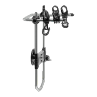
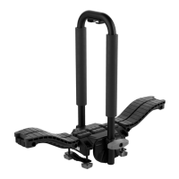
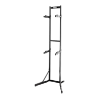
Component for supporting bike, quantity 4.

End Caps

Various sizes of end caps for the structure, quantities 6 and 4.

Hardware Components

Includes knobs, screws, washers, and leveling glides for assembly.

Structural Elements

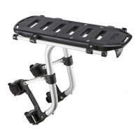
Main frame parts including top half, bottom legs, and support braces.

Installation Step 1a

Base Assembly Alignment

Position foot base, cross support brace, and structure bottom leg correctly.

Securing Base Components

Attach foot base and bottom leg to cross support brace using screws and washers.

Installation Steps 1b & 2

Attaching Base Support Brackets

Secure base support brackets to structure legs and foot base with screws.

Connecting Structure Halves

Slide the structure top half onto the tops of the structure bottom legs.

Installation Steps 3a, 3b & 3c

Mounting Bike Support Arms

Attach bike support arms to vertical side bars, adjusting height as needed.

Securing Bike Support Arms

Turn arms clockwise to lock them onto the vertical side bars.

Finalizing Arm Attachment

Insert and tighten knob through the top C-shaped tab of the support arm.

Installation Step 4

Attaching Leveling Glides

Screw leveling glides into the bottom of the foot base.

Mounting Bike Holder Cradles

Slide cradles onto support arms, indent facing up, adjust horizontally.

Loading Bikes

Weight Capacity and Adjustment

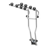
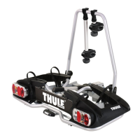
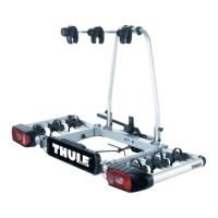
Supports two bikes up to 70 lbs. Adjust arm height by loosening knobs.

Bike Placement Guidance

Place heavier bike on bottom arms. Slide cradles to avoid interference.

Related product manuals