Step 1
1.Install the Bearings into the Flybar Control Lever.
2.Secure the Washout Linkage to the Flybar Control Lever and make sure that the Washout
Linkage can be rotated freely.
3.Secure the Linkage Balls to the Flybar Control Lever.
The inner hole is for beginner, and the outer hole
is for 3D flying.
4.Secure the Flybar Control Lever to the
Washout Base.
5.Make sure that the Flybar Control
Lever can berotated freely.
No.
1
2
Material No. Description Qty No.
1
2
3
Material No. Description Qty
1
1
2
No.
1
2
3
Material No. Description Qty
2
4
2
(2)
(4)
(3)
(2)
(3)
(1)
(5)
(6)
(8)
(9)
(3)
(4)
(3)
(1)
(2)
(6)
(5)
(3)
CONTENTS
Step 1
1.Slide in the Seesaw Hub to the Main Rotor
Hub.
2.Mind the direction of the Seesaw Hub.
No.
1
2
3
4
5
6
Material No. Description Qty
2
1
2
4
2
2
No.
7
8
9
10
11
Material No. Description Qty
2
2
2
2
2
(5)
(6)
No.
4
5
6
Material No. Description Qty
4
4
4
(4)
Introduction
Other Items Required
Assembling Section
Main Rotor System
Linkage Rod Installation
Main Frame Assembly
Tail Unit Assembly
Tail Boom Bracket Set
Electric System
Canopy Assembly
Main Rotor Blade Assembly
Introduction of E-CCPM Control System
Servo Connecting
Concept of Basic Setting and Adjustment
Setting Up of Linkage
Trouble Shooting
Spares Parts
Optional Parts
Heli Accessories
Specifiction and Features
2
4
5
6
12
13
18
23
27
31
32
33
36
38
42
47
49
57
58
59
BV1083
BK1045
Main Rotor Hub
Seesaw Hub
1
1
Main Shaft
Socket Screw M2x14
M2 Nut
BK1051
BK1086
HML2
BK1050
BK0906
BK1054
BK1079
HMX0409Y
HMV940ZZY
Main Rotor Pitch Housing
Feathering shaft
Flap Damper
Collar
Thrust Bearing d4xD9x4
Bearing d4xD9x4
HMV840ZZY
HMO26
HMC 26-8B
BK1203
HSP16-6N
Bearing d4xD8x3
Flat Washer d2.8xD5x0.5
Socket Screw M2.6x8
Linkage Ball (Ø3.8)
Countersunk Screw M1.6x6
BK1046
HMV520ZZW
HNU2-9Z
Mixing Lever
Bearing d2xD5x2.5
Shouldered Screw M2x9
BK1481
BK1203
HSP16-6N
Flat Washer d2xD3.7x0.5
Linkage Ball (Ø3.8)
Countersunk Screw M1.6x6
No.
1
2
3
4
Material No. Description Qty
2
2
1
1
No.
5
6
7
Material No. Description Qty
2
2
2
BK1044
HME3-3B
BK1015
BK0916
Collar
Set Screw M3x3
Flybar Control arm
Flybar
BK1203
HSP16-6N
BK0941
Linkage Ball (Ø3.8)
Countersunk Screw M1.6x6
Flybar Paddle
mini Titan E325
-7--6- -9- -11-
Main Rotor-1
Step 2
1.Turn the Seesaw Hub 90 degrees.
2.Mind the direction of the chamfer.
Step 4
Complete
chamfer
Step 3
Complete
(7)
Note:1
70mm70mm
Note:2
Diagram for Thrust Bearing Assembly
Small Internal Diameter
always go toward the
Blade
Large Internal Diameter
always go toward the
Main Rotor Hub
Step 2
Complete
Note:
(4)
T22
No.
1
2
3
4
5
6
Material No. Description QtyNo.
7
8
9
10
11
12
Material No.DescriptionQty
BV1010A
HNU2-9Z
BK1058
BK1481
BK0914
BK1203
Swashplate
Shouldered Screw M2x9
Flybar Control Lever
Flat Washer d2xD3.7x0.5
Washout base
Linkage Ball (Ø3.8)
1
2
2
4
1
2
HSP16-6N
BK1020
HME3-3B
HMV520ZZW
HSP17-7N
BK1014
Countersunk Screw M1.6x6
Main Shaft Lock Ring
Set Screw M3x3
Bearing d2xD5x2.5
Countersunk Screw M1.7x7
Washout Linkage
2
1
1
4
2
2
No.
1
2
3
Material No.DescriptionQty
(2)
(6)
(2)
(4)
(5)
(3)
(3)
(3)
(3)
(1)
BK0932
BK1063
BK0922
Ball Link 3.8x10mm
LlinkageRod 1.3x7mm
Ball Link 3.8x12mm
4
3
14
Scale 1:1
(A)
(E)
(B)
(D)
(C)
X2
(A)
X1
(B)
X2
(C)
X2
(D)
X2
(E)
Step 1
1.Assemble the Linkage Rods and the Ball Links.
2.The length is measured from the center of the Ball Links to the other.
3.You can use the following 1:1 drawing to measure the length of the rods.
Note:
No.
3
4
Material No. Description Qty
HNV2-6Z
HMV520ZZW
Shouldered Screw M2x6
Bearing d2xD5x2.5
2
2
(1)
(1)
(2)
T22
(11)
(10)
(4)
(7)
T22
(3)
(2)
(1)
T22
(5)
(2)
(3)
For 3D flying
For begineer
(10)
(11)
(6)
(7)
(4)
(12)
(1)
70mm
T22
(9)
(8)
No.
4
5
6
Material No.DescriptionQty
BK1064
BK1066
BK1065
LlinkageRod 1.3x10mm
LlinkageRod 1.3x24.5mm
LlinkageRod 1.3x29mm
2
2
2
-12--10--8-
Step 3
1.Fit the screws and the bearings.
2.Do not over tighten the screws and make
sure that the Seesaw Hub can be rotated
freely.
Step 1
Secure the Linkage Balls and fit the Bearings to the
Mixing Lever.
Step 2
1.Secure the Mixing Lever to the Seesaw Hub.
2.Do not over tighten the screws and make sure that the Mixing Lever can be rotated freely.
Step 1
1.Secure the Linkage Balls to the Flybar Control
Arm.
2.Fit the Collar to the Flybar Control Arm.
Step 2
1.Slide the Flybar through the Flybar Control
Arm and the Seesaw Hub.
2.Make sure the Flybar has equal protruding
from each side of the Seesaw Hub of 82.5mm.
3.Secure the Flybar by the Set Screws.
Step 3
1.Secure the Paddles to the Flybar.
2.Make sure that the distance from the Flybar
Control Arm to the Paddle are the same in
each side.
3.Make sure that the Paddles and the Flybar
Control Arm are paralleled. Add some CA
glue between the Paddles and the Flybar
after the Paddles are set.
Step 1
1.Secure the Linkage Balls to the Main Rotor Pitch Housing.
2.Insert the Flap Damper in the Main Rotor Hub.
3.Add some Silicon Oil or Vaseline to insert the Feathering Shaft through the Flap Damper.
4.Assemble the Main Rotor Housing and the Bearings one by one as the drawing.
5.Mind the direction of the Thrust Bearings.
6.Be sure to apply Loctite on the M2.6x8 Socket Screws.
Step 1
1.Slide the Main Rotor Hub Set on to the
Main Shaft.
2.Mind the direction of the Main Shaft.
3.Fit the Screw and the Nut to fix the Main
Rotor Hub and the Main Shaft.
Step 2
1.Fit the second Nut to prevent the Screws
coming loose.
2.Be sure to add some Loctite on the Screws.
Step 2
1.Slide in the Washout Assembly and make
sure the Pins of the Main Rotor Hub can go
through the holes of the Washout Base.
2.Then slide in the Swashplate and attach the
Washout Linkage to the inner Linkage Balls
of the Swashplate.
Step 3
1.Slide the Main Shaft Lock Ring and fix it
with a Set Screw.
2.
Mind the distance from the end of the
Main Shaft to the Lock Ring is about 70mm.
Step 2
1.Attach the rods to the main rotor system.
2.Please refer to the NOTE that the T mark on the Ball
Link should face out.
(4)
Lengths are measured
from ball link center to
ball link center.
Main Rotor-2 Main Rotor-4 Main Rotor-6
INTRODUCTION
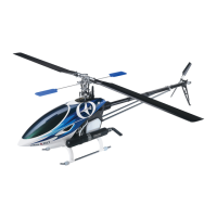
Thank you for purchasing the Thunder Tiger mini Titan E325 electric R/C helicopter.
This new helicopter is the latest innovation by Thunder Tiger. It has the perfect
combination of flying stability and the agility for 3D flying. This helicopter is an
excellent choice for flying enthusiasts like you. For convenient assembly and safe
operation of the helicopter, please read the instructions carefully. Retain the user
manual in case you need it for any information or reference.
NOTICE
1.R/C models are not toys. This product is a high-precision flying machine.
Possibilities of unexpected crashes may occur due to electronic interference,
incorrect operation, or poor mechanical maintenance. Although it is a small-
sized helicopter, the rotor blades rotate at high speeds, which may cause serious
damage, injury, or death if the model hits people or property. Therefore, extreme
caution must be exercised during operation.
2.Thunder Tiger ensures parts packaged in this product is of the highest quality.
However, after assembly and usage, parts damaged due to wear or misuse will
not be replaced under any circumstances. If you have any questions regarding
its operation and repair, Thunder Tigers service agents are able to provide free
technical guidance.
3.This product is only recommended for users ages 16 and up. Because flying
a R/C helicopter is difficult, beginners must receive guidance and supervision
from experienced pilots to minimize unexpected danger. Practice in spacious
areas, far away from obstacles such as buildings, trees, electrical towers, or
crowds.
4.To decrease the cost of repair and maintenance for beginners, it is recommended
to fly the helicopter with a practice rack and to learn basic flying skills with a
computer R/C flying simulator. (Crashes in simulators are free to repair!)
AMA INFORMATION
Operating a model helicopter requires a high degree of responsibility and skill. If
you are a newcomer to the hobby, it is best to seek help and guidance from
accomplished model helicopter pilots. This will greatly speed up the learning
process and have you flying successfully in a reasonable amount of time. We
also would strongly urge you to join the Academy of Model Aeronautics. The AMA
is a non-profit organization that provides its members with a liability insurance plan
as well as monthly magazine entitled Model Aviation. All AMA charter aircraft
clubs require all pilots to hold a current AMA sporting license prior to operation
of their models at club fields. For further information, contact the AMA at:
Academy of Model Aeronautics
5151 East Memorial Drive
Muncie, IN 47302
(317) 287-1256
FLIGHT SAFETY CHECKLIST
1.Make sure that the transmitter battery is fully charged before flying.
2.Make sure all control surfaces are operated properly before flying.
3.Do a range check of the radio before the first flight. The electronic equipment
must operate properly at a range of at least 15 meters (50 ft) even with the
transmitter antenna collapsed.
4.Make sure there are no other pilots using the same radio frequency with yours
and that there are no other radio interference on your frequency.
5.Be sure to turn on the transmitter first with the throttle stick in the idle position.
Plug the battery into the ESC last.
6.The main rotor and the tail rotor spin at very high RPM. Make sure nothing can
come in contact with the rotor blades during flight.
7.Always maintain a safe distance from the helicopter during flight.
8.Never fly the helicopter in the rain or in excessive wind conditions.
9.Always operate and fly the helicopter in a safe and responsible manner.
10.Never fly the helicopter over other pilots, spectators, cars or anything that could
result in injury or property damage.
POST FLIGHT INSPECTION
1.Inspect the model thoroughly to insure no parts have come loose or become
damaged during the flight and landing. Replace damaged parts and tighten loose
screws before flying again.
2.Clean the helicopter body.
3.Lubricate all moving parts to ensure smooth operation for the next flying.
4.Replace any worn ball links and damaged bearings.
5.Store the model in a cool, dry place. Avoid putting it under direct sunlight or
near a source of heat.
Following these simple rules will allow you to enjoy the thrill of model helicopter
flying for many years.
CAUTION
When the model has crashed, inspect the flybar, rotor shaft and the blade spindle
to make sure they are not bent. If any item is damaged, it must be replaced with
a new part to ensure safe operation. Do not glue any broken or damaged plastic
parts. Do not repair broken rotor blades. It is very important to inspect the motor,
speed control and the battery.
Always inspect the following items:
Gears, Ball links, Link rods, Bearings, Main shaft, Flybar, Spindle, Tail boom and
support, Fins, Tail rotor shaft, Belt, Main blades, Tail blades, the Motor, the Speed
control and the Battery.
Bag A
OTHER ITEMS REQUIRED
ReceiverTransmitter
(helicopter type only,
6 or more channels)
Servos
(Control Surface x3,
Rudder Servo x1)
Hex Wrench
Grease
CA GlueHobby Knife
Scissors
Gyro
Epoxy
TOOLS REQUIRED FOR ASSEMBLY
POWER SYSTEM
NipperNeedle Nose PliersScrew Driver Ball Link Pliers
Li-Po Battery
Speed Control
Brushless Motor
Battery Charger
Bag A Bag B Bag B Bag B Bag CBag D
T22
R48
Anaerobics Retainer Threadlocking
RADIO SET
Rubber Band Double Side Tap
-5--4--3--2--1-
ASSEMBLY
The parts in the mini Titan E325 kit are packed according to the assembly steps.
The part number and quantity are always shown in the square box on each page.
Do not open all the bags at once. Open only the bag that is needed for the current
assembly step.
CA GLUE
CA
(2)
(4)
(4)
 Loading...