-44-
-45- -47--46-
-49-
-51-
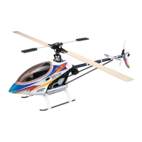
Main Frame Assembly-2
-48-
Since you have been setting the lengths of the pushrod as mentioned,
the linkage should be centered well as described below.
Centering
1. The levers should be as the drawing below while centering the
collective pitch stick.
2. Parallel the flybar, the main blades should be at 0 degree and the
swashplate should be level.
SETTING UP MAIN ROTOR COLLECTIVE PITCH ANGLE
Minimizing
1. Place the collective stick at low end.
2. The main blades should be at 10 degree and the swashplate should
be level.
Maximizing
1. Place the collective stick at high end.
2. The main blades should be at 10 degree and the swashplate should
be level.
NOTE:
1. The steps above define the limits of the collective pitch setting.
2. The setting of the maximum collective pitch depends on your personal
flying skill and style. Too much collective pitch could overload the
ESC, motor and the battery. And it will reduce the flying time also.
The following is the setting up data of pitch curve and throttle curve
for your reference only. Please ask experienced pilot to help you if
you have never done this before.
SETTING UP DATA FOR YOUR REFERENCE
Beginner
Throttle Curve
Pitch Curve
Pitch Angle
Normal
1
0
2
45
3
65
4
85
5
100
Normal
1
40
2
-
3
75
4
-
5
100
Normal
1
-2
°
2
-
3
+5
°
4
-
5
+10
°
Aerobatic Flying
Throttle Curve
Pitch Curve
Pitch Angle
Normal
Idle 1
Idle 2
1
0
80
100
2
45
-
-
3
65
70
80
4
85
-
-
5
100
100
100
Normal
Idle 1
Idle 2
Hold
1
30
20
5
0
2
-
-
-
-
3
75
75
-
-
4
-
-
-
-
5
100
95
95
100
Normal
Idle 1
Idle 2
Hold
1
-4
°
-6
°
-9
°
-10°
2
-
-
-
-
3
+5
°
+5
°
-
-
4
-
-
-
-
5
+10
°
+9
°
+9
°
+10
°
It is recommended to use a Heading Hold Gyro. With a Heading Hold
Gyro, you may not use the trim and the revolution mixing function of
tail control.
First, choose the length of the tail servo arm referring to the manual
of the Gyro. You may try 10.5mm as the starting setting. Then mount
the servo arm for the moment and check the movement of the tail
servo:
1. While giving the right rudder control, the servo arm should move
forward.
2. Rotate the helicopter with your hand counterclockwise, the servo
arm should move forward.
TAIL CONTROL AND GYRO SETUP
After making sure of moving direction of tail servo, you have to mount
the servo arm in the correct position. Please reset the receiver power
and do not move the helicopter. While the tail control stick and trim
are centered, mount the servo arm vertically. Next, two points may
be your concern:
1. The traveling limit of the tail servo may not go beyond the mechanical
movement.
2. The tail servo horn should be vertical while the tail rotor are at 0
pitch or with a little offset to the right.(Referring to the photo below)
Note
1. To find the traveling limit, you have to adjust the Gyro referring to
its manual.
2. To adjust the pirouetting speed of the helicopter, please use the
”Travel Adjustment” or the ”D/R & EXP” function.
The mini Titan E325 is an electric RC helicopter. It is strongly
recommended to use Lithium Polymer Battery. Please refer to the
following information and precaution:
1. Do use a charger that is designed for Li-Poly batteries only.
2. Do not overcharge the battery over the maximum voltage of 4.2V/per
cell.
3. Do not discharge the battery below the minimum voltage of 3.0V/per
cell.
4. Do not charge the battery unattended.
5. Do not charge the battery in a flammable circumstance.
6. If you want to store the battery for a long time, store them at 3.8V/per
cell.
Please understand the information and precaution above and that you
agree to accept the full responsibility of using the battery and any injury
caused by the battery. Thunder Tiger and its duly authorized distributors
assume no liability for damage that could occur by the improper using
of the battery.
USING OF LI-PO BATTERY
Helicopters
Q: What would you check when the helicopter shakes during flying?
A:
Q: What would you do if there comes out a lot of noise from the
helicopter during flying?
A:
Motor, Battery and Speed Controller
Q: How to choose the motor and the pinion?
A: It depends on the battery and the motor. The following is the formula
of how to calculate the wanted head speed.
Motor RPM = Motor KV x Volt(3.7V) x Series x constant (0.8)
Head Speed = Motor RPM / Gear Ratio
Gear Ratio = 150T / Motor Pinion
Example:
We choose TT OBL 29/35-10H brushless motor.
IF using a 3S(11.1V) Li-Po battery, the motor rpm should be
3500KV x 3.7V x 3S x 0.8= 31080 rpm
And we expect to have the head speed of 2600~2800rpm
31080 / Gear Ratio = 2800
Gear Ratio = 11.1
TROUBLE SHOOTING
Are the main blades out of track?
Are the paddles out of track?
Are the main blades well balanced?
Are the paddles well mounted at the same distance from the
rotor shaft?
Is the spindle or the flybar bent?
Is the main shaft bent?
Is the main rotor hub damaged?
Is the motor well installed and is the shaft of the motor bent?
Is the tail rotor shaft bent?
Is the tail rotor hub damaged?
Do all the ball bearings work well?
a. Please check the gear mesh between the main gear and the
motor pinion. If there is too much gear mesh, it would generate
a lot of gear noise during flying.
b. If the tail drive belt is too loose, it will bring about some noise
and may cause the failure of tail control.
c. Check the linkages and control system of main rotor and tail
rotor to make sure every linkage is working correctly and not
colliding with something else.
d. Check if the motor is running out of balance.
The pinion would be
150T / 11.1 = 13.51
So we choose 13T as the motor pinion.
IF using a 2S(7.4V) Li-Po battery for long time hovering, the motor
rpm should be
3500KV x 3.7V x 2S x 0.8= 20720 rpm
And we expect to have the hovering head speed of 2100rpm
20720 / Gear Ratio = 2100
Gear Ratio = 9.87
The pinion would be
150T / 9.87 = 15.20
So we choose 15T as the motor pinion.
Q: Which motor and speed control is recommended?
A: The TT OBL 29/35-10H brushless motor(No.2381) and the ACE
BLC-40(No.8041-H) speed control are recommended.
TROUBLE SHOOTING
-10°
Rudder Servo
a.
b.
c.
d.
e.
f.
g.
h.
i.
j.
k.
Rudder Servo
90°
0 25 50 75 100 Stick
100
75
50
25
Thro.
Throttle Curve
0 25 50 75 100 Stick
100
75
50
25
Pitch
Pitch Curve
0 25 50 75 100 Stick
100
75
50
25
Thro.
Throttle Curve
◎
Normal
0 25 50 75 100 Stick
100
75
50
25
Thro.
◎
Idle-up 1
0 25 50 75 100 Stick
100
75
50
25
Thro.
◎
Idle-up 2
0 25 50 75 100 Stick
100
75
50
25
Pitch
Pitch Curve
◎
Normal
0 25 50 75 100 Stick
100
75
50
25
Pitch
◎
Idle-up 1
0 25 50 75 100 Stick
100
75
50
25
Pitch
◎
Idle-up 2
0 25 50 75 100 Stick
100
75
50
25
Pitch
◎
Hold
-43- -50- -52-
PV0701
MAIN ROTOR HUB
PV0705
MAIN ROTOR GRIP
PV0709
FLYBAR(2)
PV0713
WASHOUT BASE
PV0717
UPPER BRG HOUSIN
PV0721
PHASE CONTROL TRACK
PV0702
FLYBAR SEESAW HUB
PV0706
FLAP DAMPER(70°)
PV0710
SWASHPLATE
PV0714
MAIN FRAME
PV0718
SERVO TRAY
PV0722
AUTO-R TAIL DRIVE GEAR
PV0703
FLYBAR CONTROL LEVER
PV0707
FEATHERING SHAFT(2)
PV0711
WASHOUT BASE SET
PV0715
BASE PLATE
PV0719
BATTERY TRAY
PV0723
MAIN GEAR (W/BEARING)
PV0704
MAIN SHAFT(2)
PV0708
FLYBAR CONTROL ARM
PV0712
MIXING LEVER
PV0716
LANDING SKID
PV0720
BODY RETAINING POST(2)
PV0724
MAIN GEAR ONLY 50T
PV0725
M.G. HEX DRIVE HUB
PV0729
PINION 13T(2)
PV0733
TAIL DRIVE GEAR SET
PV0737
TAIL ROTOR SHAFT(2)
PV0741
TAIL ROTOR HUB
PV0745
MAIN ROTOR BLADE, 315mm
PV0726
ONE WAY SHAFT
PV0734
TAIL BOOM(2)
PV0738
TAIL PITCH CONTROL SET
PV0742
TAIL ROTOR
PV0746
SKID DAMPER
PV0727
M. SHAFT LOCK RING(2)
PV0731
PINION 15T(2)
PV0735
TAIL DRIVE BELT, MXL413T
PV0739
TAIL PITCH CONTROL LINK(4)
PV0743
TAIL FIN SET
PV0747
TAIL SERVO TRAY
PV0728
MOTOR MOUNT
PV0732
TAIL BOOM BRACKET
PV0736
TAIL UNIT CASE SET
PV0740
TAIL ROTOR GRIP
PV0744
FLYBAR PADDLE
PV0748
DOUBLE JOINT LEVER
PV0749
TAIL P. CONTROL LEVER
PV0753
TAIL LINKAGE ROD
PV0757
CANOPY
PV0761
THREADLOCKING, T22
PV0765
BODY MOUNT RUBBER
PV0769
THRUST BEARING(2), d4xD9x4
PV0750
TAIL P. CONTROL SLIDER
PV0754
LINKAGE ROD SET
PV0758
BODY ONLY
PV0762
TAIL ROD GUIDE
PV0766
DECAL
PV0770
BEARING(10), d2xD5x2.5t
PV0751
TAIL SUPPORT BRACKET
PV0755
BALL LINK, 3.8
PV0759
BLADE HOLDER
PV0763
LINKAGE BALL 3.8(20)
PV0767
ANTENNA TUBE SET
PV0771
BEARING(4), d4xD9x4t
PV0752
TAIL SUPPORT
PV0756
BODY SET
PV0760
ANAEROBICS RETAINER, R48
PV0764
COUNTER SCREW, M1.6x6(20)
PV0768
RUBBER BAND AND NYLON STRAP SET
PV0772
TAPPING SCREW (W/WASHER), M2x6
PV0773
TAPPING SCREW (W/WASHER), M2x10
PV0777
SOCKET SCREW(20), M2x8
PV0781
SCREW BAG
PV0774
SHOULDERED SCREW, M2x9
PV0778
SOCKET SCREW(20), M2x10
PV0782
SOCKET SCREW BAG
PV0775
SOCKET SCREW(20), M2x14
PV0779
SOCKET SCREW(20), M2x25
PV0776
SOCKET SCREW(20), M2x16
PV0780
SET SCREW(20),M3x3
(20)
(20)
(20)
(10)
(10)
(20) (20)
(20)
(20) (20) (20)
E325 SPARE PARTS
(2)
(12)
PV0212
SOCKET SCREW(20),M3x10
PV0049
BALL BEARING,d3xD8xW4
PV0257
SOCKET SCREW(20),M3x20
PV0236
LOCK NUT(20),M3
PV0048
BALL BEARING,d4xD8xW3
PV0234
NUT(20),M2
PV0783
SOCKET SCREW(20),M2.6x8
(20)
(20) (20)
(20) (20)
(20) (20)
(20)
(20) (20) (10)

 Loading...