Page 7<&(%$*4.8"4,7%H'*#$"&8#I%/7*,#*%4,77%JKLLLKLMMKNOPO1Item 63585
?@<6AQRS6;@ACRED@CEA6E@ET6 ?6AFS
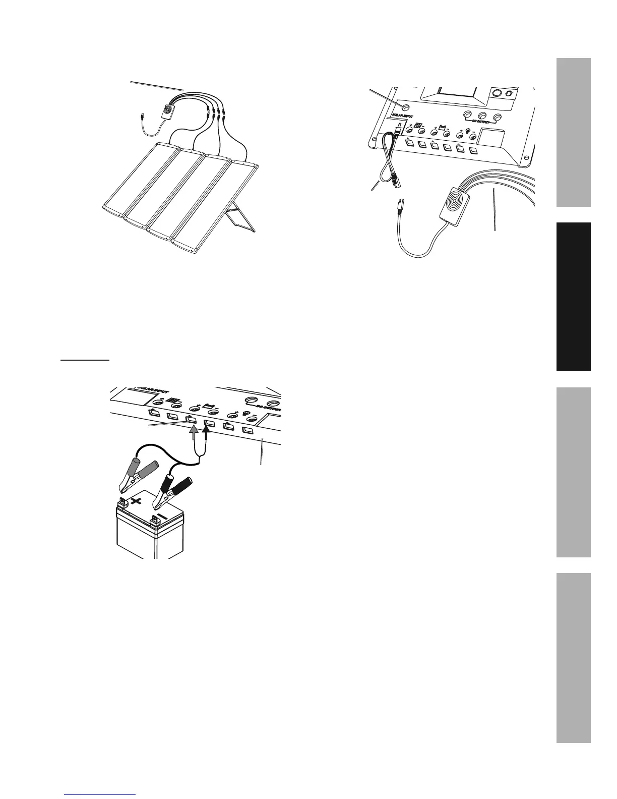
7. Connect end of lead wires coming from the Solar
Panels (1) to the Splitter Cable (2). See Figure F.
?/7"$$*(%
T,+7*#%\^]
<"3'(*%<
8. Connect the wires of the Battery
Clamps to the battery terminals on the
bottom of the Charge Controller.
9. Attach the Battery Clamps to the battery’s
terminals. (Battery not included.)
U@;ECEVd%%Connect red connector to positive (+).
Connect black connector to negative (-). Unit will not
function with reverse connection. See Figure G.
W,$$*(>%A*(5"8,7#
T.,(3*%
T&8$(&77*(%\e]%
<"3'(*%V
10. Connect Splitter Cable to the DC connector
cable. Plug DC cable into Solar Input jack
on the Controller. See Figure H.
?&7,(%
C8/'$
?/7"$$*(%T,+7*%\^]
XT%T&88*4$&(
T,+7*%\L]
<"3'(*%B