OPERATING MANUAL 3. PRODUCT DESCRIPTION
ThyssenKrupp Aufzugswerke GmbH 17
3.2 Functional description
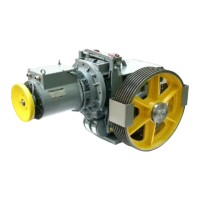
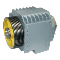
Machine TW130 has a single-stage worm gear with flanged-on three phase
motor.
A flexible coupling integrated in the brake disk is used as motor - worm shaft
connection. The drive shaft is driven by the worm wheel. At the shaft end an
overhung traction sheave is attached.
The drive shaft has rolling bearings. For the horizontally positioned motor
design, the rolling bearings of the worm shaft are oiled through the wheel
teethes submerged in the oil sump of the gear housing. With motors
positioned vertically the worm shaft is partly oil-submerged. The gear oil level
can be checked using an oil gauge glass.
The setting of the side contact pattern center of the toothing may be changed
to a certain extent at the factory.
Gear housing:
The monobloc gear housing has a flange-connected motor. The traction
sheave shaft comes with an integrated bearing bracket on one side to
minimize the forces acting on the shaft. The opposite second bearing bracket
is fit in through a bearing hole and screw-connected to the housing.
Variants with traction sheave on the right or on the left are available,
dependent on where the machine is used.
The cast gear housing is made of EN-GJL 250. It is prepared for right hand
or left hand motor designs.
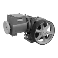
Drive motor:
TW130 is available with a frequency-controlled three-phase drive in design
IMB5/V1 as standard (flange-connected with 2 bearings).
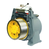
The drive can be operated by hand using a handwinding wheel attached at
the motor shaft end (BS).
An encoder located on the motor shaft between motor and handwinding
wheel monitors the motor speed. Details see manufacturer's information in
chapter 8.
Tailor-made motors in IMB5/V1 design can be used optionally.
Motors in 4/16 and 6/24-pole design for pole-changing (AC2) or phase-
shift operation (ACVV)
All types of special motors (explosion-proof variant, special tailor-made
variants, for example).
The mechanical design (flange dimensions, AS / BS shaft end, encoder,
handwinding wheel or flywheel rim hub) must comply with the requirements
set out in BV 6530 – 05 / sheets 3-7.
Details on motors see chapters 3.7 – 3.9.