Do you have a question about the ThyssenKrupp DAF380 and is the answer not in the manual?
Explains pictograms and designations used in the manual.
Details obligations of operator, installation firm, and personnel for safe operation.
Defines correct usage of the DAF380 and limitations.
Excludes liability for damage arising from improper use or non-compliance with manual.
States that changes void the warranty and affect safety.
Highlights risks of operating in enclosed rooms and handling revolving parts.
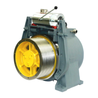
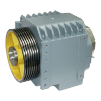
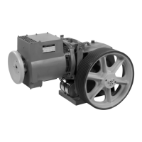
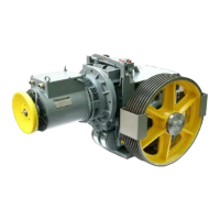
Illustrates and lists the components of the DAF380 drive.
Explains the DAF380's design as an asynchronous motor and its performance ranges.
Details the temperature sensor in the motor winding for monitoring.
Describes the incremental encoder for controlling the DAF380.
Lists optional accessories required for operation and maintenance.
Explains the dual-circuit outer shoe-type brake installed on the motor housing.
Describes the optional machine base frame for setup and its components.
Specifies the required environmental conditions for the drive's location.
Provides technical specifications for the DAF380, including dimensions and protection.
Presents detailed dimensional drawings of the DAF380 machine.
Details the optional machine base frame and the arrangement of isolation elements.
Describes the incremental hollow shaft encoder and its technical data.
Details the pin assignment and explanation for the encoder connector.
Provides technical data for the optional second encoder, type HTL.
Details the specifications and operation of the double-vane magnet.
Provides technical data for the forced ventilation system of the DAF380.
Describes how the DAF380 is packaged for transport.
Details safety regulations and procedures for transporting the machine.
Provides guidelines for safe transport using a forklift.
Outlines safety precautions and methods for crane transport.
Informs where to find weight data and dimensions on the packaging.
Instructs on checking delivered parts for completeness and damage.
Details how to document and report transit damage.
Provides information on proper disposal of packaging materials.
Gives instructions for storing the assembly before installation.
Specifies required environmental conditions for intermediate storage.
Details the setup and alignment of the machine and base frame.
Explains the process of mounting the machine onto the base frame.
Describes how to arrange ropes on the traction sheave for single and double wrap.
Explains how to adjust the machine's position and alignment.
Provides wiring diagrams for motor, temperature monitoring, and fan connections.
Shows terminal box details for the CSA version of the motor.
Illustrates the terminal connections for the brake test switch.
Shows the terminal connections for the double-vane magnet.
Depicts the terminal connections for the blower motor.
Lists essential checks before putting the machine into operation.
Highlights importance of functioning brake monitoring for upward overspeed.
Outlines the annual maintenance tasks and safety regulations for qualified personnel.
Specifies the lubrication quantity and type for the motor shaft bearing.
Details the procedure for uniform grease distribution in bearings.
Explains how to check and set the brake shoe stroke.
Details the basic setting of brakes and initial tension distance.
Provides steps for setting the brake test switch and checking its function.
Details the setting procedure for the brake test switch in the CSA version.
Explains that factory settings for the double-vane magnet nut must not be altered.
Provides a step-by-step guide for disassembling and replacing brake shoes.
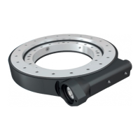
Details the disassembly and installation process for replacing the traction sheave.
Guides through the disassembly and installation of the encoder.
Details the process of installing the encoder onto the motor shaft.
Explains how to check for and classify grease or oil leaks.
Provides emergency steps to release the car from safety gear engagement.
Illustrates and describes attaching the hydraulic jack for car release.
Describes the motor snubber for limiting switching surges.
Lists tightening torques for various screw dimensions and strengths.
Lists optional accessory parts for emergency deployment and maintenance.
Describes the handwinding wheel used for manual movement of the elevator.
Details the procedure for using the rope clamp for securing ropes.
Explains the deployment and use of the blocking clamp for ropes.
Describes the mounting and deployment of the pressure arm.
Details the mounting and deployment of the hydraulic jack for lifting the car.
Confirms the safety component meets essential safety requirements as per the EC directive.
Defines the application and permissible parameters for the brake device.
Lists permissible brake moments for different DAF types.
Specifies maximum tripping speeds and rated speeds for traction sheaves.
Relates rotary speeds to car speeds and suspension for traction sheaves.
Outlines conditions for using the brake device with overspeed detection systems.
Details requirements for brake device integration with overspeed governors.
Specifies monitoring of brake circuits and prevention of movement on failure.
Describes actions to take if the machine moves despite brake engagement.
Contains general remarks and clarifications about the brake device's function.
Notes the brake element's redundant design and sensor monitoring.
Excludes examination of wear and tear effects on brake torques.
Clarifies that this type-examination covers specific requirements for unintended car movement.
Confirms safety component conformance to examination basis and scope of application.
Details nominal brake torques and response times for different DAF sizes.
Provides tables of brake torques and response times for DAF models.
Lists features like power type, brake control, air gap, and overexcitation.
Outlines conditions for using the safety component with other systems.
States the safety component is part of a protective system requiring a triggering component.
Specifies the component's use as an ascending car overspeed protection and drive brake.
Requires installers to create examination instructions and provide tools.
Addresses lift system dimensions related to brake torques and deceleration.
Emphasizes considering traction and variance for braking distance calculations.
Requires installers to confirm compliance with examined component specifications.
States self-monitoring must prevent starting the lift in case of a fault.
Provides remarks on the brake element's redundant design and sensor monitoring.
Notes the brake element's redundant design and sensor monitoring.
Excludes examination of wear and tear effects on brake torques.
Clarifies that this type-examination covers specific requirements for unintended car movement.
Confirms the safety device complies with the tested safety device and directive.
Lists products eligible for CSA Mark with indicators 'C' and 'US'.
Specifies elevator equipment classification for CSA certification.
Specifies elevator equipment certified to U.S. standards.
Describes the three-phase motors, their type, voltage, frequency, and insulation class.
States drive motors are certified as component parts for other installations.
Clarifies that the control unit is not included in this examination.
Specifies that the drive motor is intended for short-duty operation.
Specifies Canadian/CSA standard for motors and generators.
Specifies UL standard for electric motors.
Provides mechanical details like housing, shaft, and attachment for the encoder.
Lists electrical parameters such as power supply, current consumption, and output.
Details accuracy parameters such as phasing and pulse on/off ratio.
Specifies environmental conditions like ESD, vibration, and temperature ratings.
Shows the pin configuration and function for the encoder's connector.
Emphasizes that assembly must be performed by qualified personnel only.
Advises maintaining distance from interference sources for proper encoder function.
Provides contact information for technical support in Germany and other countries.
| Model | DAF380 |
|---|---|
| Output Current | 380 A |
| Control Type | Digital |
| Cooling Method | Forced Air |
| Protection Class | IP20 |
| Type | DC Drives |
| Input Voltage | 380-480 VAC |