FUNCTION CHARACTERISTICS
56
NA10 - Manual - 04 - 2022
ON the Disable IE>> by start IE>>> (IE>>disbyIE>>>) parameter available inside the Set \ Profile
A(or B) \ Residual overcurrent-50N/51N \ IE>>> Element \Setpoints menu.
All the named parameters can be set separately for Profile A and Profile B (Set \ Profile A(or B) \
Residual overcurrent-50N/51N \ IE> Element (IE>> Element, IE>>> Element) \ Setpoints menus).
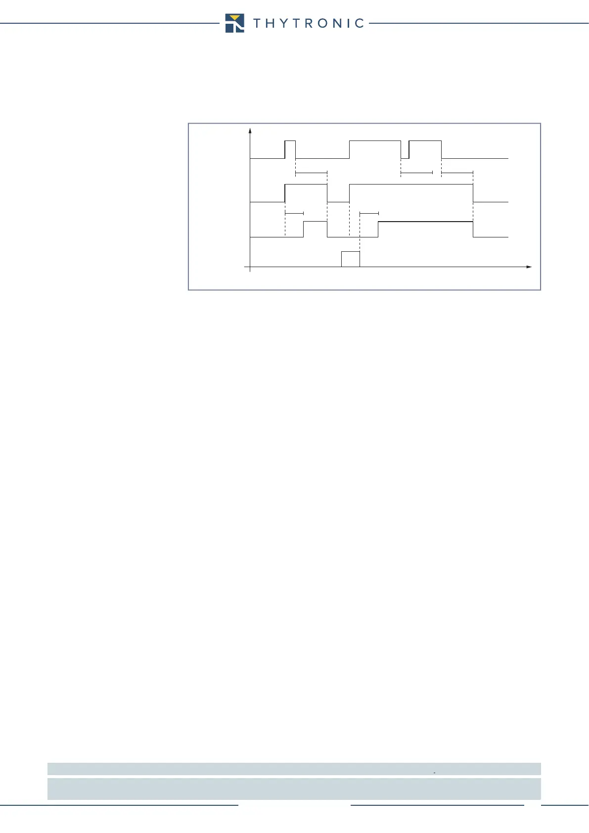
An adjustable reset time delay is provided for every threshold t
E>RES
, t
E>>RES
, t
E>>>RES
).
Each residual overcurrent element can produce the Breaker Failure output if the IE> BF, IE>> BF
and/or IE>>> BF parameters are set to ON. The parameters are available inside the Set \ Profile
A(or B) \ Residual overcurrent-50N/51N \ IE> Element (IE>> Element, IE>>> Element) \ Setpoints
menus.
[1]
For all overcurrent elements, a block from the second harmonic restraint may be set by setting ON
the IE>2ndh-REST, IE>>2ndh-REST, IE>>>2ndh-REST parameters inside the Set \ Profile
A(or B) \ Residual overcurrent-50N/51N \ IE> Element (IE>> Element, IE>>> Element) \ Setpoints
menus.
If the CLP function (Cold Load Pick-up) is enabled for element blocking, the selected threshold may
be blocked for an adjustable time interval, starting from the circuit breaker closure.
This operating mode may be select by setting ON-Element blocking the IECLP> Mode, IE-
CLP>> Mode, IECLP>>> Mode parameters.
If the CLP function (Cold Load Pick-up) is enabled for threshold change, the selected threshold may
be changed for an adjustable time interval, starting from the circuit breaker closure.
This operating mode (ON-Change setting = IECLP> Mode, IECLP>> Mode, IECLP>>>
Mode) and the concerning operating time within the CLP (tECLP>, tECLP>>, tECLP>>>) may be
adjusted inside the Set \ Profile A(or B) \ Residual overcurrent-50N/51N \ IE> Element (IE>> Element,
IE>>> Element) \ Setpoints menus, whereas the operating thresholds within the CLP ( IECLP>def,
IECLP>inv,....) may be adjusted inside the Set\Profile A(or B) \ Residual overcurrent-50N/51N \
IE> Element (IE>> Element, IE>>> Element) \ Definite time (Inverse time) menus.
For every of the four thresholds the following block criteria are available:
Logical block (Block1)
If the IE>BLK1, IE>>BLK1 and/or IE>>>BLK1 enabling parameters are set to ON and a bi-
nary input is designed for logical block (Block1), the concerning element is blocked off whenever
the given input is active.
[2]
The enabling parameters are available inside the Set \ Profile A(or B) \
Residual overcurrent-50N/51N \ IE> Element (IE>> Element, IE>>> Element) \Setpoints menus, while
the Block1 function must be assigned to the selected binary input inside the Set \ Inputs \ Binary
input IN1(2) menus.
Selective block (Block2)
All along the protective elements the selective block may be set.
The logic selectivity function may be performed by means any combination of the following I/O:
• One committed pilot wire input (BLIN1).
• One or more binary inputs designed for input selective block.
• One committed pilot wire output (BLOUT1).
• One or more output relays designed for output selective block.
Only when the committed pilot wire are used the continuity check of the pilot wire link is active.
Use of committed pilot wire input BLIN1:
• The protection is blocked off according the selectivity block criteria when the input BLIN1 is active.
The information about phase or phase+earth block may be select programming the ModeBLIN1
parameter inside the Set \ Profile A(or B) \ Selective block-BLOCK2 \ Selective block IN menus.
Use of binary inputs:
Note 1 The common settings concerning the Breaker failure protection are adjustable inside the Breaker Failure - BF menu.
Note 2 The exhaustive treatment of the logical block (Block 1) function may be found in the “Logic Block” paragraph inside CONTROL AND MONITOR-
ING section
Timers-F50N-51N.ai
IE> element residual overcurrent (50N/51N) - Timers
IE> Start
IE> Trip
t
E>
t
E>
RESET
INPUT
t
E>RES
t
E>RES
t
E>RES
t