INSTALLATION
85
NV10B - Manual - 04 - 2022
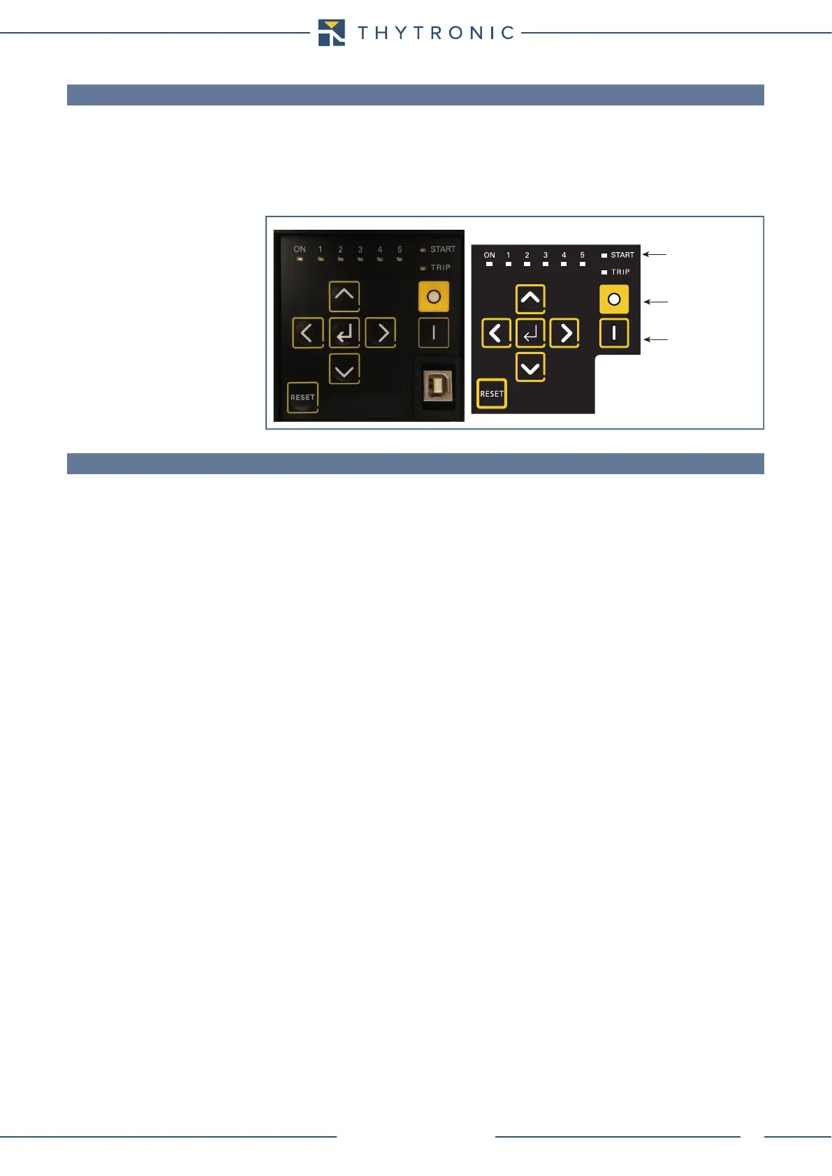
6.4 LED ALLOCATION
Following indicator LEDs are available on the front panel:
• LED ON (green): if no diagnostic anomalies are detected, the green LED is turned ON while any
fault is highlighted by flashing.
• LEDs 1...5 (red) are freely assignable from the user to any protective and/or control functions.
• LED START (yellow) committed for start information of any protective functions.
• LED TRIP (red) committed for trip information of any protective functions.
6.5 FINAL OPERATIONS
Before energizing the electric board, it is advisable to check that:
• The auxiliary voltage in the panel falls within the operative range of Pro_N relays.
• The relay rated voltage (100 V or 400 V) corresponds to the Pro_N input voltages.
• All wirings are correct.
• All screws are tightly screwed.
Led
CB Open
CB Close