33
SME2-IS - Manual - 06- 2021
FUNCTIONAL CHARACTERISTICS
This function has four adjustable thresholds with programmable tripping time.
• the rst threshold, which can be set to directional/non-directional, is time-dependent pursuant to
IEC 60255-3/BS142
• the second, third and fourth thresholds, with characteristic settable to directional (67)/non-direc-
tional, are time-independent.
The fault signal (TS51A) is supplied to the remote control unit via the closing of a contact connected
to terminal 2 of the MB terminal block and to the communications interfaces.
Operating logic
and regulations
The overcurrent protection compares the fundamental component of each of the three phase cur-
rents (I
L1
, I
L2
, I
L3
) with the set thresholds; if at least one of the three phase currents exceeds its
threshold, the threshold and the respective timer start. If the threshold violation persists, when its
tripping time expires, the threshold trips (TRIP), otherwise the threshold is reset.
The rst threshold I>
inv
is time-dependent with the following characteristic curves:
• IEC 255-3/BS142 type A or SIT, inverse time: t = 0.14 · t>
inv
/ [(I/I>
inv
)
0.02
- 1]
• IEC 255-3/BS142 type B or VIT, very inverse time: t = 13.5 · t>
inv
/ [(I/I>
inv
) - 1]
• IEC 255-3/BS142 type C or EIT, extremely inverse time: t = 80 · t>
inv
/ [(I/I>
inv
)
2
- 1]
• LIT long inverse time: t = 120 · t>
inv
/ [(I/I>
inv
)
- 1]
Where:
t: tripping time
I>: tripping threshold
t>
inv
: tripping time regulation (T
P
)
The second (I>>
def
), third (I>>>
def
) and fourth thresholds (I>>>
def
) are time-independent.
The following applies to all the above time-dependent characteristics:
• The minimum tripping current is 1.1 times the set threshold (asymptotic reference time).
• The characteristics are defined between 1.1 and 20 times the set threshold;
[1]
if threshold regula-
tion exceeds 0.22 I
n
, the upper limit of the measurement range is 4.5 I
n
.
• The minimum tripping time t is 0.1 s.
• For time-independent tripping characteristics, the upper limit of the measurement range is 4.5 I
n
(2250 A).
The second, third and fourth thresholds, which can be set to directional or non-directional, are
time-independent with adjustable threshold, tripping time and tripping characteristic angle:
Each protection threshold can be enabled or disabled,
[2]
with the following defaults:
• The rst threshold (51.S1) is disabled with I>
inv
= 0.04 I
n
(20 A), NIT type time-dependent character-
istic and tripping time t>
inv
= 0.12 s
• The second threshold (51.S2) is enabled with I>>
def
= 0.50I
n
(250 A), characteristic angle ThetaP>>-
def
= 0 degrees and tripping time t>>
def
= 0.50 s
• The third threshold (51.S3) is enabled with I>>>
def
= 1.00I
n
(500 A), characteristic angle ThetaP>>>-
def
= 0 degrees and tripping time t>>>
def
= 0.10 s
The second harmonic restraint block is active for all three thresholds.
A constant reset time can be set for each of the thresholds t>
RES
, t>>
RES
, t>>>
RES
and t>>>>
RES
Note 1 For input values greater than 20 times the threshold, the tripping time is limited to the value corresponding to 20 times the threshold
Note 2 If the threshold is disabled (Enable = OFF) the trip command is not available but it still contributes to the internal logic
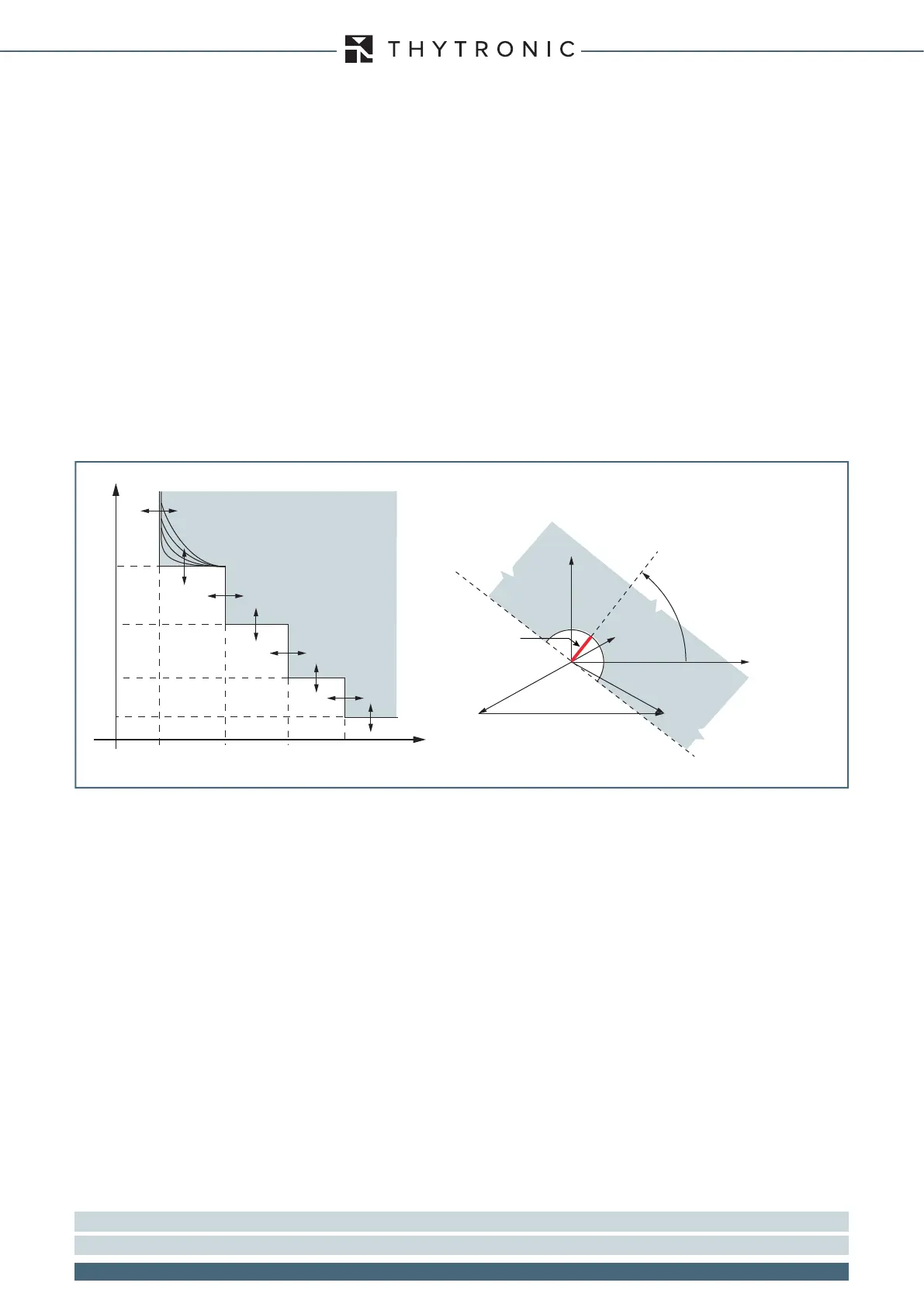
Tripping characteristic of the thresholds of the overcurrent function - 50/51
Example phase L1
Tripping threshold:
(I>>, I>>>, I>>>>)
Characteristic angle:
(ThetaP>>, ThetaP>>>, ThetaP>>>)
Characteristic semi-axis
Non-actuation sector
U
23
U
23
I
L1
U
L2
U
L3
U
L1
Actuation sector
I
I>> I>>>
t>
t>>
t>>>
I>
t
I>>>>
INTERVENTION
t>>>>