52
52
SME2-IS - Manual - 06 - 2021
FUNCTIONAL CHARACTERISTICS
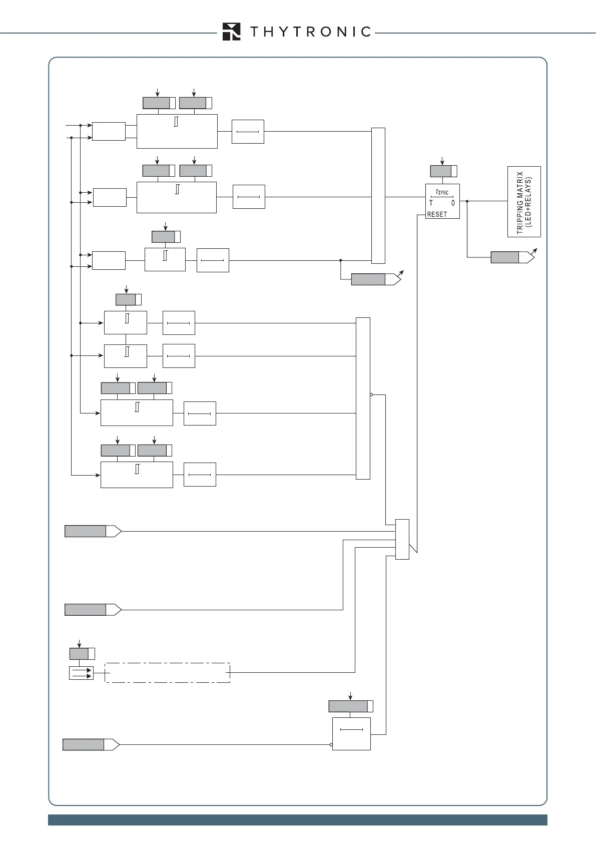
Functional diagram of the synchronisation check function (25) for synchronous grids
“1” with
∆
f less than df
-GRID
(grids synchronous)
t
SYNC
∆
f
≤
df
-GRID
df
-GRID
value ∆
(V1≥V2)
&
Sync
Sync-net
&
V
1
V
2
Sync-TR-K
Sync-TR-L
value ∆f
value ∆V
∆
V
≤
dV
12-SYNC
dV
12-SYNC
dp
12-SYNC
dp
12-SYNC
dV
21-SYNC
(V2≥V1)
∆
V
≤
dV
21-SYNC
t
STAB
0T
t
STAB
0T
t
STAB
0T
∆
≤
dp
12-SYNC
∆
≤
dp
21-SYNC
t
STAB
0T
t
STAB
0T
f
1
=
f
n
±
f
range
f
range
f
2
=
f
n
±
f
range
t
STAB
0T
t
STAB
0T
“1” with V
1
in the range V
min
-
SYNC
to V
max
-
SYNC
“1” with f
1
in the range
(f
n
-
f
range
) and (
f
n
+
f
range
)
“1” with
∆
V
less than the threshold
“1” with
∆
less than the threshold
“1” with f
2
in the range
(f
n
-
f
range
) and (
f
n
+
f
range
)
“1” with V
4
in the range V
min
-
SYNC
to V
max
-
SYNC
V
min
-
SYNC
V
min
-
SYNC
≤
V
1
<
V
max
-
SYNC
V
max
-
SYNC
V
min
-
SYNC
V
min
-
SYNC
≤
V
4
<
V
max
-
SYNC
V
max
-
SYNC
Rof>SYNC
STOP-SYNC
“1” with unstable frequency measurement (block)
≥
Reclosing
Reclosing sequence started by internal command
(MMI or interface)
“1” with synchrocheck stop active (internal command)
52a
Binary input INx
“1” with breaker closed
timeout-
SYNC
timeout-
SYNC
0T
RESET