64
64
SME2-IS - Manual - 06 - 2021
MEASUREMENTS, LOGICAL STATES AND COUNTERS
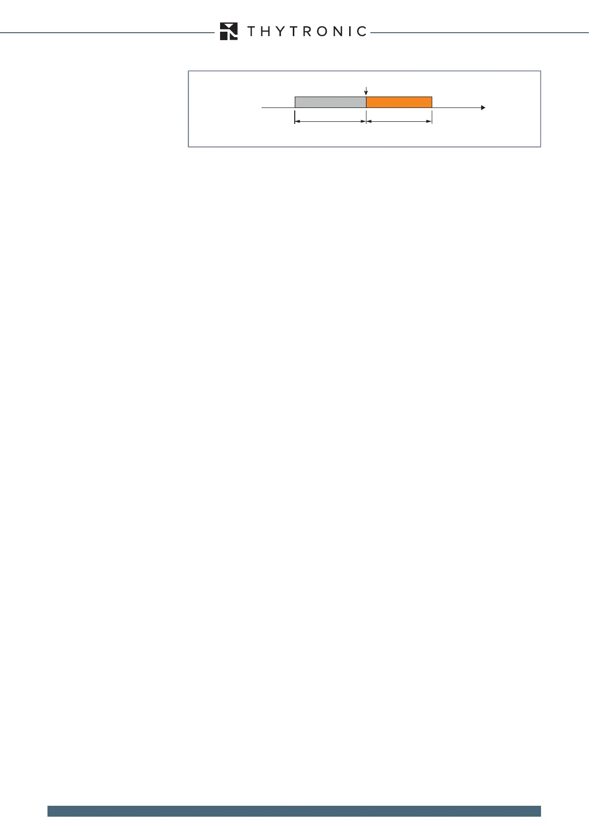
• Set the pre-trigger and post-trigger intervals
• Select the sampled measurements to be logged.
• Assign the analogue measurement channels (1...12) to the measurements to be logged.
• Assign the digital measurement channels (1...12) to the measurements to be logged (status of
output relays / logical inputs).
• Select the signals which trigger logging; the measurements are saved automatically when the user
selected signal changes state (start / trip of a protection function, change of state of output relays/
logical inputs).
COMTRADE
The logs are saved in the COMTRADE (Common Format for Transient Data) format; this is an IEEE
standard (C37.111) which denes the format for the les and the logging criteria for transient fault
data in electrical power systems.
The standard also denes the structure of the header le (.HDR), conguration le (.CFG) and data
le (.DAT) use to exchange data.
The standard is included as IEC 60255-24 in the collection of standards governing protection relays;
for a complete treatment of the COMTRADE format, please refer to the respective literature.
The les can be analysed with the Thyvisor software or with a standard compliant visualiser.
The number of recordings that can be saved is variable, depending on the user dened conguration
of the following parameters:
• Pre-trigger time and post-trigger time.
• Number of channels assigned to the measured values.
Number of recordings congurable
Recording method cyclic
Sampling frequency 32 samples per period
Trigger settings:
• Pre-trigger time 0.05...1.00 s
• Post-trigger time 0.05...60.00 s
• Output triggers K1...K5
• Input triggers IN1...IN6
• Manual control Thyvisor, remote control
Sampled channel settings:
• Instantaneous currents i
L1
, i
L2
, i
L3
, i
E
• Instantaneous phase voltages u
L1
, u
L2
, u
L3
, u
E
Measurement channel settings (Analogue 1...12):
• Frequency f
• Phase currents I
L1
, I
L2
, I
L3
• Calculated residual current I
E
• Phase voltages U
L1
, U
L2
, U
L3
• Calculated residual voltage U
E
• Phase-to-phase voltages U
12
, U
23
, U
31
• Phase shift (I
L1-
U
L1,
I
L2-
U
L2,
I
L3-
U
L3
) Phi
L1
, Phi
L2
, Phi
L3
• Phase shift (I
L1-
U
23,
I
L2-
U
31,
I
L3-
U
L3
) Alpha
1
, Alpha
2
, Alpha
3
• Phase shift (U
E-
I
E
) Phi
E
• Forward and reverse sequence voltage U
1
, U
2
• Phase current second harmonic I
L1-2nd
, I
L2-2nd
, I
L3-2nd
• Maximum percentage ratio of phase current second harmonic/fundamental component I
-2nd
/I
L
Digital channel settings (Digital 1...12):
• Input status UD, RVS, Anin, caX89, ccX89 (IN1...IN6)
• Output status K1...K5
trigger.ai
Trigger oscillografia
Trigger
Time
pre-trigger post-trigger