4
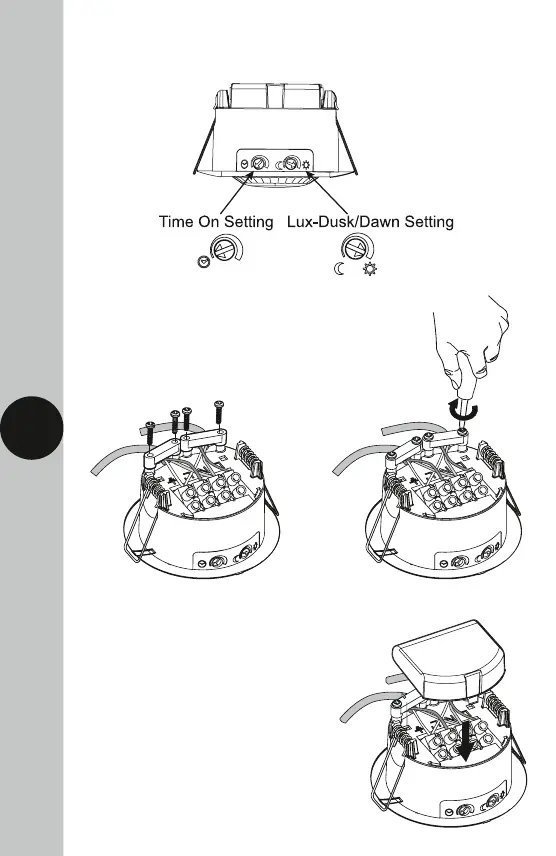
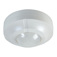
• The adjustment knobs located beneath the sensor head are factory-set
to “Test Mode”. Double check they are set as follows;
• Replace both cable clamps previously removed,
using the 4 cable clamp screws, to secure the
mains supply and load cables to the sensor.
Do not overtighten the screws.
• Reposition the wiring cover
onto the sensor and click
into place.