5
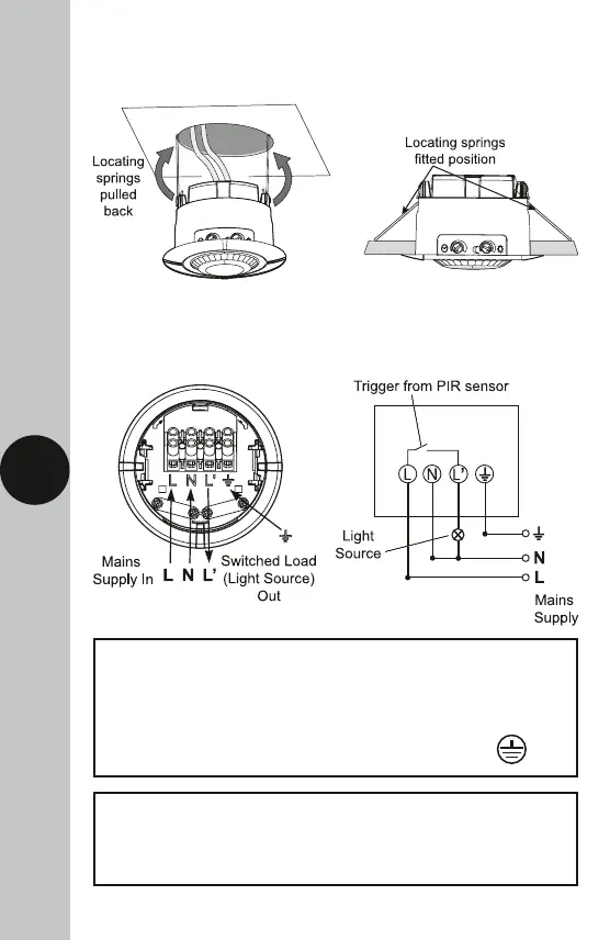
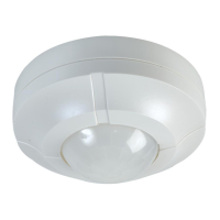
• Push back the locating springs and feed the unit into the ceiling void
via the 75mm hole. The locating springs will now fold back and hold
the SLFM360N in place.
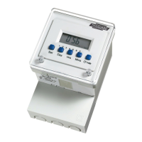
6. Connection Diagram
• Connect the cables as follows;
Switched Load (Light Source) Out
Switch Live (Brown or Red) to L1
Neutral Load (Blue or Black) to N
230V 50Hz Mains Supply
Live Supply (Brown or Red) to L
Neutral Supply (Blue or Black) to N
A ‘Loop Terminal’ is provided should a 3 core
cable be used which is marked