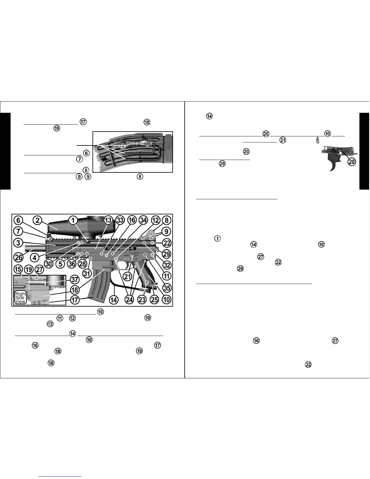
TOOLS: The magazine contains Tools and lubricating oil for your marker.
6)
❏
To remove the magazine from the magazine base press the
magazine button
(on right side of the magazine base), then slide
magazine down and out. Store
tools in magazine after use (shown
with 2 allen wrenches and oil.
To reinstall drive assembly parts and lower receiver:
1)
❏
Clean inside upper receiver and removed parts.
2)
❏
Inspect and replace any damaged parts. Lubricate
❏
the front bolt
o-ring,
❏
the rear bolt o-ring,
❏
the linkage arm and the drive spring/
guide pin with a few drops of Tippmann
®
paintball marker oil (or other
premium paintball marker oil) before reinstalling them.
3)
❏
Insert valve into power tube with Tombstone cutout aligned down to
match power tube cutout. (Insert tombstone adapter to check fit).
4)
❏
Insert reassembled parts - front bolt, power tube/valve, rear bolt/rear
bolt plug, with linkage arm facing up, until tombstone adapter can be
inserted, long push pin
replaced and velocity screw can be
accessed. You may need to jiggle marker while sliding parts in.
5)
❏
Insert the guide pin into the drive spring and
❏
drive spring into the
rear bolt plug.
❏
Insert the end cap, while keeping the guide pin centered
in it.
❏
Install the upper end cap short push pin .
• To remove the lower receiver (grip) :
❏
Remove the 2 long lower
receiver push pins
/ and pull the lower receiver from the
upper receiver
.
Receiver Disassembly
❏
Eye protection designed for paintball use must be worn by the user and
any person within range.
•
To access trigger parts:
❏
Pull left plate off trigger
assembly
. Do not remove the 5 dowel pins from
the right plate. See trigger assembly on page 9.
•
To remove trigger assembly from the lower receiver (grip):
❏
Rotate the Safety Selector Switch straight up
and
❏
pull it out left side of lower receiver.
❏
Pull up on
the trigger assembly
keeping it intact.
•
To remove the gas line / Tombstone from the upper receiver:
❏
Remove the lower receiver see above.
❏
Remove the long
push pin
from the upper receiver.
❏
Remove the magazine from
the magazine base by pressing the magazine button (on right side
of magazine base), then slide magazine down and out.
❏
Slide
magazine base
back until it stops, then down.
❏
Pull down on gas
13
12
Drive Assembly Removal and Installation
NOTE: It is not necessary to disassemble the upper receiver to access
and service the drive assembly internal parts.
To remove the drive assembly parts: front bolt, power tube, valve, rear
bolt/rear bolt plug, linkage arm, drive pin guide, drive spring and end cap
(parts shown on pages 8 and 9).
1)
❏
Remove air supply before any disassembly: Unload marker, remove
the air supply as outlined on page 10 and put the marker in the uncocked
position before beginning to disassemble it. To uncock the marker, hold
the bolt cocking handle back 3/4 - then pull the trigger and release handle
forward
which will uncock the marker.
2)
❏
Remove gas line and lower receiver (grip) see Receiver
Disassembly instructions on page 12.
3)
❏
Screw velocity screw in past receiver.
4)
❏
Remove last push pin (short) holding end cap in place.
5)
❏
Pull end cap out and tilt marker up, drive assembly parts should
slide out the back. You may need to jiggle marker while sliding parts out.
Receiver Disassembly / Assembly
(continued on page 13)
Receiver Disassembly / Assembly
(continued on page 14)
Receiver Disassembly / Assembly (continued from page 12)Receiver Disassembly / Assembly (continued from page 11)
7)
❏
To remove the Front Sight :
Remove Front Sight Screw
and slide the front sight off .
8)
❏
To remove the Rear Sight :
Remove 2 rear sight screws
/ and the Rear Sight .
❏
FIRST: perform steps 1), 2), 3), 4), 5), 6), 7) and 8) as outlined on
pages 11 and 12 before beginning Receiver Disassembly.
line to remove the gas line/Tombstone. NOTE: If you remove the
gasline from the Tombstone, when reinstalling, inspect and oil the o-ring
and be careful not to overtighten and strip threaded parts.
E
N
G
L
I
S
H
E
N
G
L
I
S
H