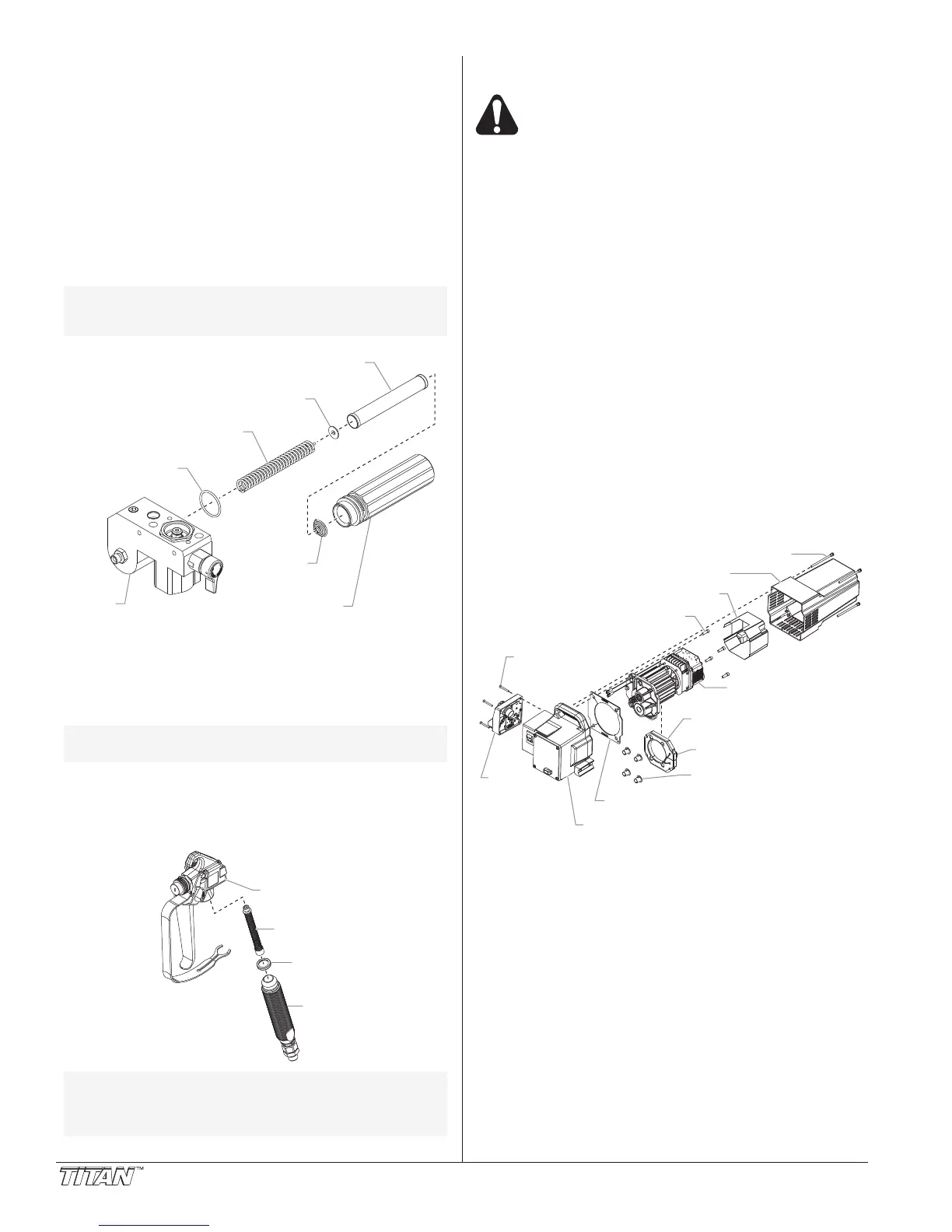
Replacing the Filters
Pump Filter
1. Loosen and remove the filter housing by hand.
2. Slip the filter off of the filter support spring.
3. Inspect the filter. Based on inspection, clean or replace
the filter.
4
. Inspect the o-ring. Based on inspection, clean or replace
t
he o-ring.
5. Slide the new or cleaned filter over the filter support
spring with the adapter in place. Push the filter into the
center of the pump block.
6. Slide the filter housing over the filter and thread it into the
pump block until secure.
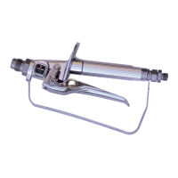
Gun Filter
1. Move the gun trigger lock to the unlocked position.
2. Loosen and remove the handle from the gun body.
3. Turning clockwise, unscrew the filter from the gun body.
4. Turning counterclockwise, screw the new or cleaned filter
into the gun body.
5.
Make sure the handle seal is in position and thread the
handle into the gun body until secure.
6. Move the gun trigger lock to the locked position.
NOTE: For more detail, part number information, and
complete assembly drawings, please see the
LX-80
II
Professional
Airless Gun Owner's
Manual (P/N 313-2293).
Handle
Handle
Seal
Filter
Gun
Body
NOTE: Left-handed threads require turning the filter
clockwise to remove.
Pump
Block
Filter
Spring
Filter Housing
Seal
Filter Support
Spring
Filter
Adapter
NOTE: The filter housing should be hand-tightened,
but make sure the filter housing is seated fully
into the pump block.
10 © Titan Tool Inc. All rights reserved.
Replacing the Motor
Electrostatic discharge (ESD) potential could
cause damage to electronic control. Use Titan
ESD wrist strap P/N 700-1037 or equivalent when
working on electronic control with electronic
cover removed.
1. Unplug the unit.
2
. Loosen and remove the four motor shroud screws.
R
emove the motor shroud.
3. Release the tie wrap on the side of the baffle assembly
and slip the baffle assembly off of the motor. Remove the
four baffle spacers.
4. Slide the electronic cover off of the electronic control
assembly on the motor.
5. At the electronic control assembly on the back off the
motor, disconnect the wire coming from the potentiometer
and the wire coming from the transducer. Also,
disconnect the two wires coming from the control panel
board (refer to the electrical schematic in the Parts List
section of this manual).
6. Remove the four control panel mounting screws. Pull
back the control panel for access to the control panel
board.
7. At the the control panel board, disconnect the two wires
coming from the motor (refer to the electrical schematic in
the Parts List section of this manual).
8. Loosen and remove the four motor mounting screws.
9. Pull the motor out of the gear box housing.
10. With the motor removed, inspect the gears in the gear box
housing for damage or excessive wear. Replace the
gears, if necessary.
10.
Install the new motor into the gear box housing. Make
sure the housing gasket is positioned properly
.
1
1. Secure the motor with the four motor mounting screws.
12. Reconnect the wires to the electronic control assembly
(refer to the electrical schematic in the Parts List section
of this manual).
13. Position the electronic cover over the electronic control
assembly.
14. Position the control panel on the gear box housing and
secure in position using the four control panel mounting
screws.
15.
Slip the baffle assembly around the motor. Secure the
baf
fle assembly with the tie wrap. Slip the four baffle
spacers into position between the rear bell of the motor
and the baf
fle assembly
.
16.
Slide the motor shroud over the motor
. Make sure the
housing gasket is positioned properly
.
17.
Secure the motor shroud with the four motor shroud
screws.
Tie Wrap
Baffle Spacers
Baffle Assembly
Control Panel
Mounting
Screw
Gear Box Housing
Housing Gasket
Control
Panel
Motor Shroud Screw
Motor Shroud
Electronic Cover
Electronic Control
Assembly
Motor Mounting
Screw
 Loading...