ST-1000-D1 LIGHTING CONTROLLER UNIT
- 3 -
Configuration
Connections
For ST-1000-D1 to operate properly, the unit terminals must be connected correctly.
The terminals voltage polarity must be followed accordingly to prevent damage to the
unit.
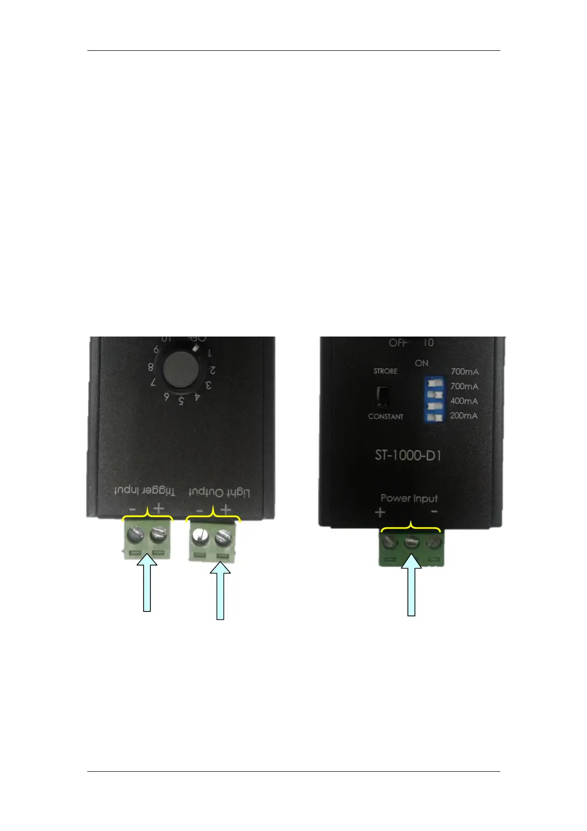
Board Power Terminals
These terminals are to be connected to a 24V DC power supply with minimum
500mA capability.
Lightings Output Terminals
These terminals are to be connected to 24V-Lightings for a 24V DC power supply
at Lightings Input Power Terminals.
Trigger Input Terminals
For Trigger Mode operation, these terminals are to be connected to trigger signal
line from external control unit. Trigger voltage range from 5V to 24V DC.
For Constant Mode operation, these terminals can be left unconnected.
LEFT VIEW: RIGHT VIEW:
Lightings Output
Terminals
Trigger Input
Terminals
(5V to 24V DC)
Board Power
Terminals
(24V DC)
 Loading...