Document Ref 947571-001 Rev 2 Page 5-21
Quantium 110 & 210 Installation Manual Installation
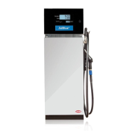
SIDE A
Terminal 1 U+ extern
Terminal 2 Volume A
Terminal 3 Volume B
Terminal 4 GND extern
Terminal 5 Release gnd extern
Terminal 6 Release input extern
Terminal K1-3 Nozzle +24V extern
Terminal K1-4 Nozzle GND extern
b2
b1
a1
a1a1
b2
5
a2
1
6
b2
a2
2
a2
3
b1
5
1
b1
6
7
3
2
a1
b2
a2
4
b1
8
4
1 hose : 8 core signal cable
Terminal Rail
3
1
-
4
5
+
2
K1
8 way connector
(EPS/Tatsuno,
LOG)
Installation
cable
1
5
3
2
4
7
6
8
8 way connector
(Nuovo Pignone only)
3
8
7
6
5
4
1
2
Installation
cable
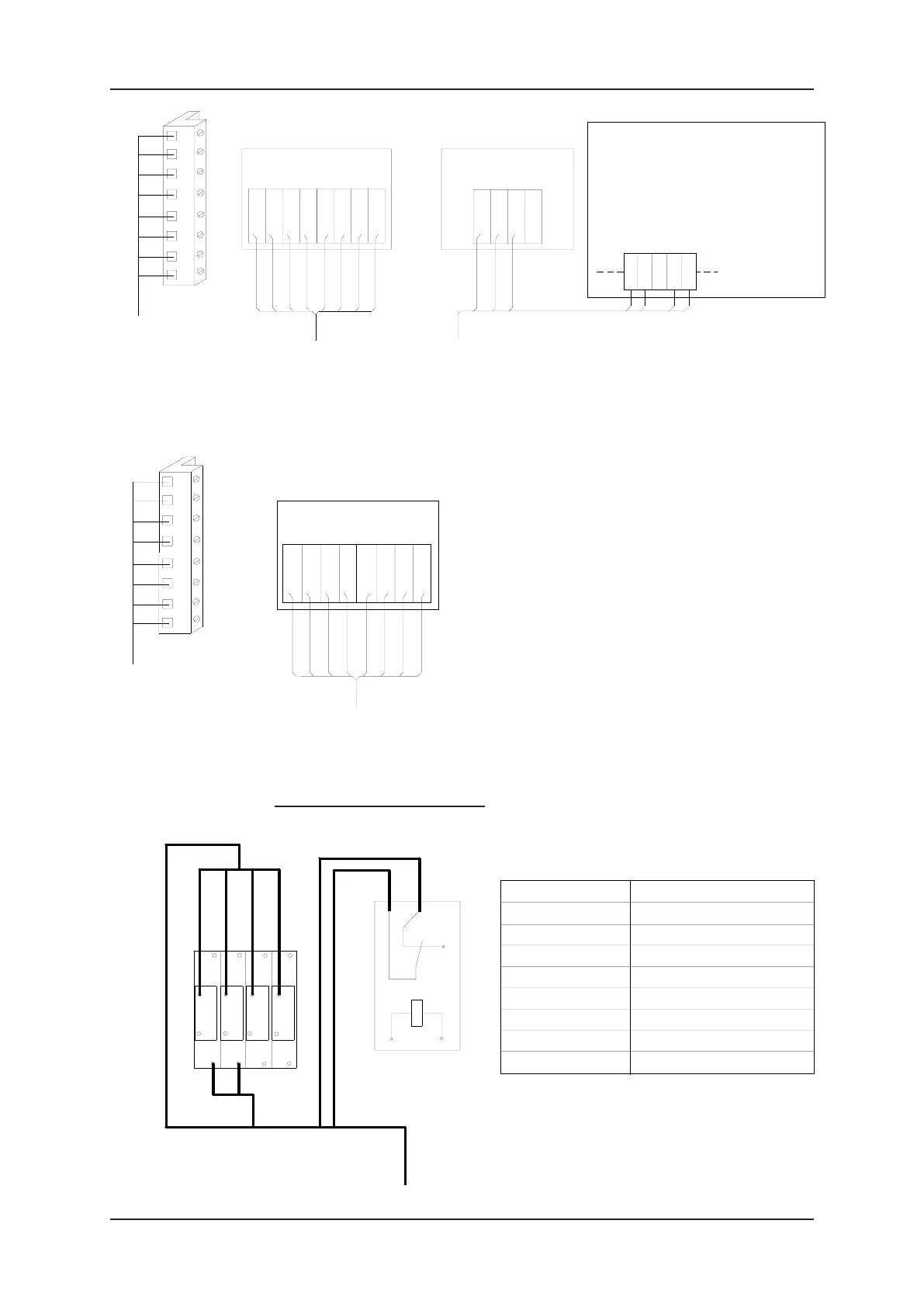
Comms Board
EPS
8 7 6 5
RT+
RT-
RR+
RR-
EPS / TATSUNO
4 3 2 1
LT+
LT-
LR+
LR-
Mainboard X101
Connect wire link between: -
GPIN2 to VBU for Product Position menu not available
VBU to GPIN1 for Auto Mode dispenser (disconnect
wire in shop)
4 3 2 1
VBU
GPIN1
GPIN3
GPIN4
GPIN2
*
Comms Board
LOG
IL
IH
OH
OL
LOG
*
4x2x0.5mm²
screened cable
Explanation Mainboard X101:-
VBU = 24V
GPIN1 = Auto/Manual
GPIN2 = Product Position
GPIN3 = Low Level Left
GPIN4 = Low Level Right
4x2x0.5mm²
screened cable
4x2x0.5mm²
screened cable
Comms Board
NUP
5 6 7 8
NUOVO
PIGNONE
TxB-1
1 2 3 4
RxB-1
RxA-1
RxA-2
RxB-2
TxA-1
TxA-2
TxB-2
Fleet Interface (Q100T only)