Page 5-22 Document Ref 947571-001 Rev 2
Installation Quantium 110 & 210 Installation Manual
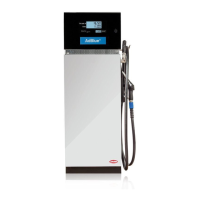
WIRED INTO COMMS JUNCTION BOX
1) Follow the instructions given in section 4.6 to access the hydraulic area. Locate
the relevant Comms Junction Box in the hydraulic area.
2) Unlock the four screws on the junction box cover and remove completely.
3) Locate the relevant terminal rail inside the relevant junction box.
Note : The Comms are always located in a separate Bernstein Junction
Box.
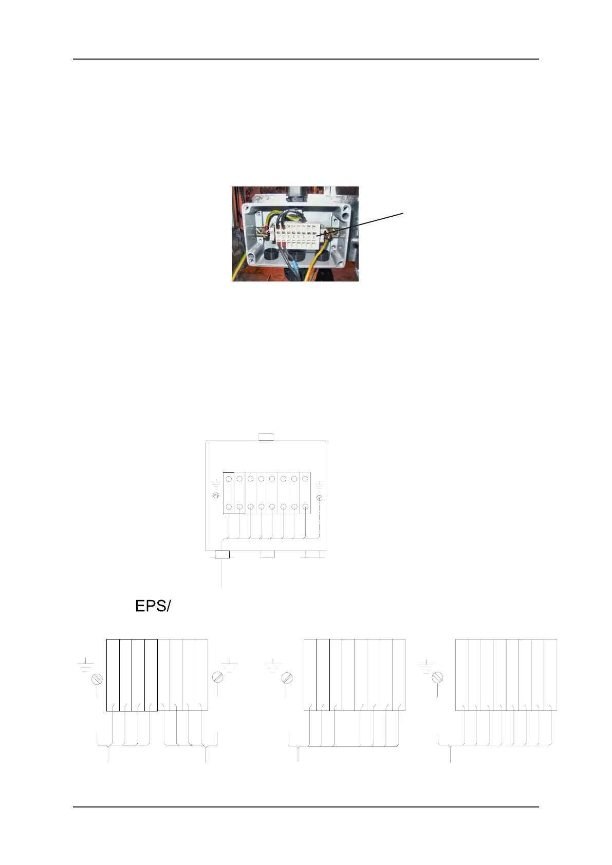
4) Make the connections according to the correct wiring diagram shown in this
section.
IMPORTANT :- ENSURE THE CORRECT WIRING DIAGRAM IS
FOLLOWED.
5) When complete, re-fit the junction box cover.
6) Ensure that all tools and unused materials are removed, close the hydraulic
door and lock.
7) Re-instate power to the dispenser and test its operation.
4 core
shielded cable
RT-
1 2 3 4 5 6 7 8
LT-
4 core
shielded cable
RR+
RR-
LR+
LR-
RT+
LT+
TATSUNO
screen
screen
NUOVO
PIGNONE
8 core
shielded cable
RxB-2
RxB-1
TxA-2
TxB-2
RxA-2
RxA-1
TxB-1
TxA-1
screen
8 core
shielded cable
TTD
24V
Prod Pos
Low Lev R
Aut/Man
Low Lev L
TTC
GND
LOG
1 2 3 4 5 6 7 8
brown
brown
white
white
green
green
yellow
yellow
screen
8 TERMINAL COMMS
(EPS/Tatsuno, Nuovo
Pignone, LOG, Metax)
Installation cable
Comms Terminals in
Bernstein Junction Box
1 2 3 4 5 6 7 8
Terminal Rail in
Comms Junction Box