10
side of each hinge. Then, insert the hinges into the
wing. When all the hinges are in, working quickly,
coat the other end of the hinges with epoxy. Then,
join both fl aps. Do your best to wipe away any excess
epoxy. Move the fl aps up and down several times to
align all the hinges. Set the wing panels aside and
allow the epoxy to harden.
❏ 6. Join the outboard fl aps and ailerons to the outboard
wing panels the same way using fresh batches of
epoxy. Note that the ailerons use small hinges.
❏ 7. After the epoxy on all the hinges has hardened,
move the fl aps and ailerons up and down several
times to get them moving smoothly and easily.
We’ll install the servos and hook up the fl aps and
ailerons later.
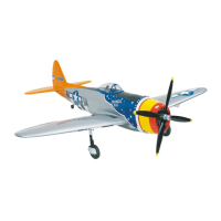
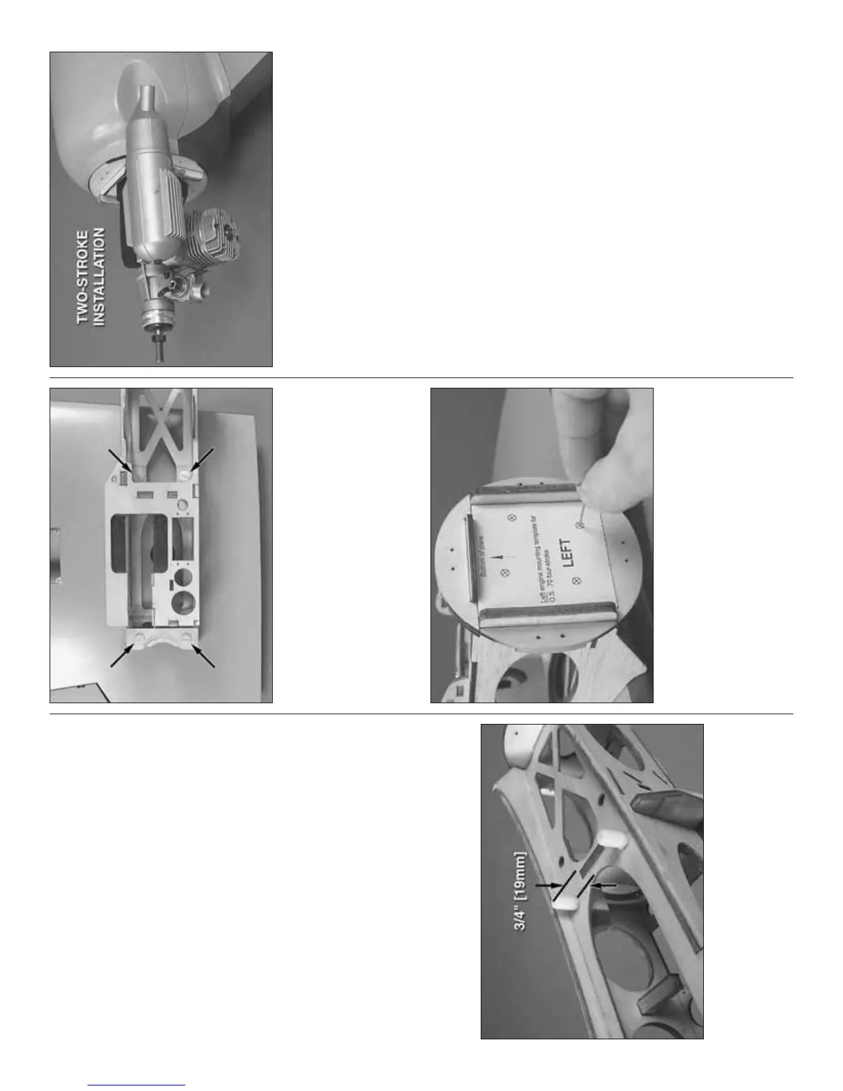
MOUNT THE ENGINES
❏ 1. Use medium CA or epoxy to glue two 8 x 30mm
grooved nylon alignment pegs into the holes in
each engine nacelle. Be certain the peg indicated
protrudes above the base of the nacelle approximately
3/4" [19mm].
❏ ❏ 2. After the epoxy from the previous step has
hardened, use four 1/4-20 x 2" [50mm] nylon bolts
(indicated by the arrows in the photo) to mount the
left engine nacelle to the bottom of the left inboard
wing panel.
❏ ❏ 3. Read the note following this step. Then, cut
out the left Engine Mounting Template (since we’re
doing the left nacelle fi rst) from the back of the manual
for the type of engine you will be using—two-stroke
or four-stroke. Use tape or spray adhesive to hold the
template to the fi rewall. Then use a sharpened piece
of wire or a large T-pin to mark the center of the holes
in the template into the fi rewall.
Note: The four-stroke template is for the O.S. Max .70
Surpass and the two-stroke template is for an O.S.
Max .40 or .50 two-stroke. Since the engine mounts
are adjustable, they should fi t other engines in the
size range, but if you are using engines different than
O.S. the positioning of the mounts may have to be
rotated slightly to align the muffl er with the muffl er
cutout in the fi berglass nacelle cover. If this is the
case, you’ll have to mount your engine to the mount
before marking the holes in the fi rewall. Then, place
the nacelle cover over the nacelle on the wing panel
and position the mount (with the engine) so the
muffl er fi ts in the muffl er cutout.
❏ ❏ 4. Once the engine mount holes have been
marked, drill 5/32" [4mm] holes through the fi rewall
at each mark. Remove the template. Push 4-40 blind
nuts into the holes in the back of the fi rewall—if
necessary, trim away any plywood that interferes with
the blind nuts.