11
❏ ❏ 5. Loosely mount the engine mount to the fi rewall
with 4-40 x 3/4" [19mm] socket-head cap screws
(SHCS) and #4 fl at washers. Adjust the mount to fi t
your engine. Tighten the screws to pull the blind nuts all
the way into the back of the fi rewall. Temporarily clamp
the engine to the mount so the front of the drive washer
will be 5" [127mm] from fi rewall. Use a Dead Center
™
Engine Mount Hole Locator (GPMR8130) or another
method to mark the holes in the mount for the engine
mounting screws. NOTE: The 3/4" [19mm] screws
holding the mount to the fi rewall are intentionally short
so they do not cut into the front of the fuel tank. Later,
when mounting the engine for the fi nal time, you will
be instructed to add threadlocker to the threads of the
screws so they do not come loose.
❏ ❏ 6. Remove the engine from the mount and take
the mount off the fi rewall. Add a few drops of thin
CA to the edges of the blind nuts in the back of the
fi rewall so they won’t come out.
❏ ❏ 7. Drill #29 holes at the marks you made in the
engine mount halves for mounting the engine. Tap 4-
40 threads into the holes. Remount the mount to the
fi rewall and mount the engine to the mount with four
4-40 x 3/4" [19mm] SHCS, #4 lock washers and #4
fl at washers.
❏ 8. Mount the other engine to the right nacelle the
same way. Make sure you use the right engine mounting
template for marking the holes in the fi rewall.
HOOK UP THE THROTTLE AND
INSTALL THE FUEL TANK
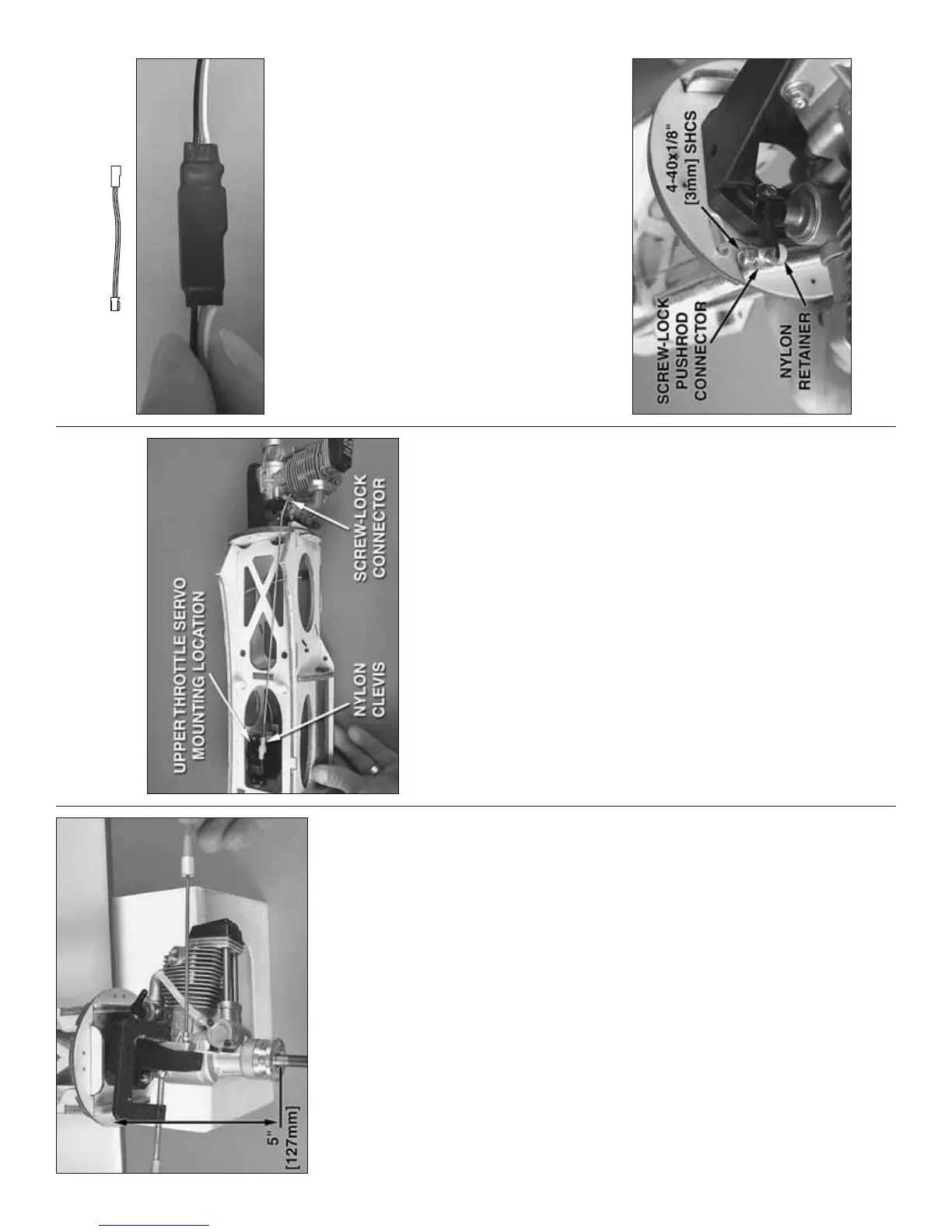
Refer to this photo while hooking up the throttle.
The throttle servo may be mounted in either of two
locations depending on the location of the carburetor
arm on your engine. For most two-stroke engines, it
will be easiest to mount the throttle servo in the lower
location (the location in the bottom of the nacelle next
to the landing gear mount). For some four-stroke
engines (such as the O.S. Max .70 illustrated in this
manual), it will be easiest to mount the throttle in
the upper location (as shown in the photo). If using
the O.S. Max .70, the carburetor will also have to be
reversed to position the carburetor arm on the top.
If using the O.S. .70, remove the engine, reverse
the carburetor and carb arm, and then remount the
engine. However you decide to hook up the throttle,
make certain the pushrod will not interfere with the fuel
tank when it is in position later (you could temporarily
fi t the fuel tank while working on the throttle).
❏ ❏ 1. Center the throttle servo by temporarily
connecting it to the receiver with a battery and turning
on the radio with the throttle trim on the transmitter
centered. Cut off the unused servo arms so there is
one arm remaining.
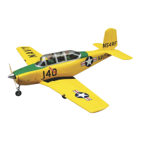
6" [150 mm]
SERVO EXTENSION
❏ ❏ 2. Connect a 6" [150mm] servo extension to the
throttle servo. (There are diagrams on pages 48-49
that show all the servo extensions that were used.) Cut
a piece of the 3/8" x 3" [10 x 75mm] black heat shrink
tubing in half and fi t it over the connection between
the servo wire and the extension. Carefully shrink the
tubing with heat from a heat gun or a lighter.
❏ ❏ 3. Place the throttle servo in the mounting
location you will be using—if using the upper throttle
servo mounting location shown, the nacelle will have
to be removed from the wing. Use the mounting holes
in the servo as a guide to drill 1/16" [1.6mm] holes for
the servo mounting screws that came with the servo.
Temporarily mount the servo with the screws. Then,
remove the screws and servo. Add a few drops of
thin CA to each screw hole, allow to harden, and then
remount the servo.
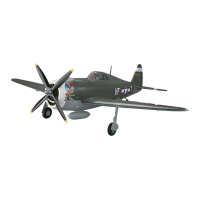
❏ ❏ 4. Hook up throttle using a 2-56 x 17-1/2"
[445mm] pushrod and a nylon clevis on the servo
 Loading...