12
end and a brass screw-lock connector with a nylon
retainer and a 4-40 x 1/8" [3mm] socket-head cap
screw (SHCS) on the carburetor arm. Cut a slot in the
fi rewall for the throttle pushrod. Bend the pushrod as
necessary to connect to the carburetor arm.
❏ ❏ 6. For installing the fuel tank, mounting the
fi berglass nacelle cover and mounting the landing
gear, it will be easier to have the engine out of the
way. Remove the engine mount from the fi rewall and
set the engine aside.
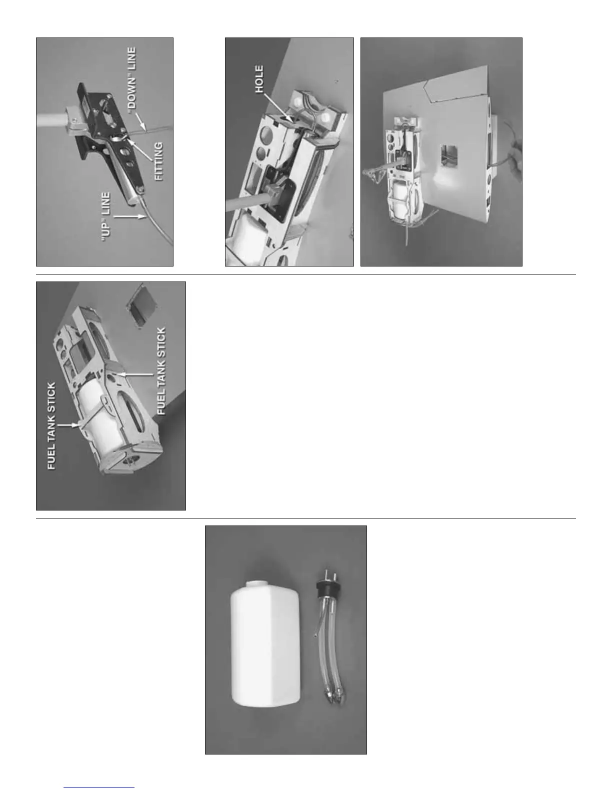
❏ ❏ 7. Assemble both fuel tanks—a three-line setup
is recommended—one for the vent/pressure line going
to the muffl er, one for fuel pickup to the carburetor and
a third line for fueling/defueling. This setup will allow
fueling and defueling without having to disconnect
any lines from the carburetor and without having to
turn the model upside-down. To set up the fuel tank
this way, cut two of the aluminum tubes to a length of
1-3/8" [35mm] and leave the other, longer tube as-is.
Assemble the stopper assembly with the aluminum
tubes, bend the longer vent tube upward so it will be
at the top of the tank, and then cut the silicone lines
to the correct length so the clunks will not contact the
rear of the tank. Connect the lines to the tubes in the
stopper and fi t the stopper into the tank and tighten
the screw. Make sure the clunks do not contact the
rear of the tank; otherwise, they could get stuck.
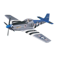
❏ ❏ 8. Mount the left nacelle to the wing with the nylon
bolts. Fit the fuel tank into the nacelle. Then, install and
glue two 3/8" x 3-1/16" [10 x 78mm] plywood fuel tank
sticks from the laser-cut plywood sheet into the slots
to hold the fuel tank in position. Note: Even though fuel
lines appear in a few of the following photos, there’s
no need to connect them until later after the cowl has
been mounted—the manual will instruct you later.
❏ 9. Return to step 1 and mount the engine, hook up
the throttle and install the fuel tank in the right nacelle
the same way.
MOUNT THE MAIN LANDING GEAR
RETRACT INSTALLATION
(If not mounting retracts, skip to “Fixed Gear
Installation” on the next page.)
Same as we’ve been doing so far, start with the left,
inboard wing panel.
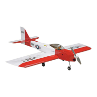
❏ ❏ 1. Determine which color of air line you will be
using for the “up” line and which color you will be
using for the “down” line—the up line connects to the
fi tting on the back end of the air cylinder and the down
line connects to the fi tting on the front of the cylinder
that comes out of the side. Cut the up line to a length
of 21" [530mm] and cut the down line to a length of
18" [460mm].
❏ ❏ 2. Connect the lines to the air cylinder. Rotate
the fi tting on the down line as shown so it will be
easier to fi t the gear between the rails.
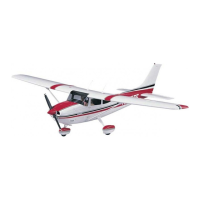
❏ ❏ 3. Install the retract and guide the air lines through
the hole in the bottom of the panel, past the fl ap servo
hatch and out root end of the panel—note that the up line
goes through the hole in the back of the nacelle fi rst.