13
❏ ❏ 4. Holding the retract centered in the rails with
the strut retracted so it will be out of the way, drill four
7/64" [2.8mm] holes for the mounting screws. Mount
the retract with four #6 x 1/2" [13mm] Phillips screws.
❏ ❏ 5. Use a rotary tool with a fi ber-reinforced cutoff
wheel to cut the one of the main landing gear axles
that came with the retracts to the correct length. File
a fl at spot on the axle for the set screw that mounts
the axle to the strut. Mount the wheel with a drop of
threadlocker on the set screw. Add a drop of oil to
both sides of the wheel at the strut and the axle.
❏ 6. Mount the other retract to the right inboard wing
panel the same way.
FIXED GEAR INSTALLATION
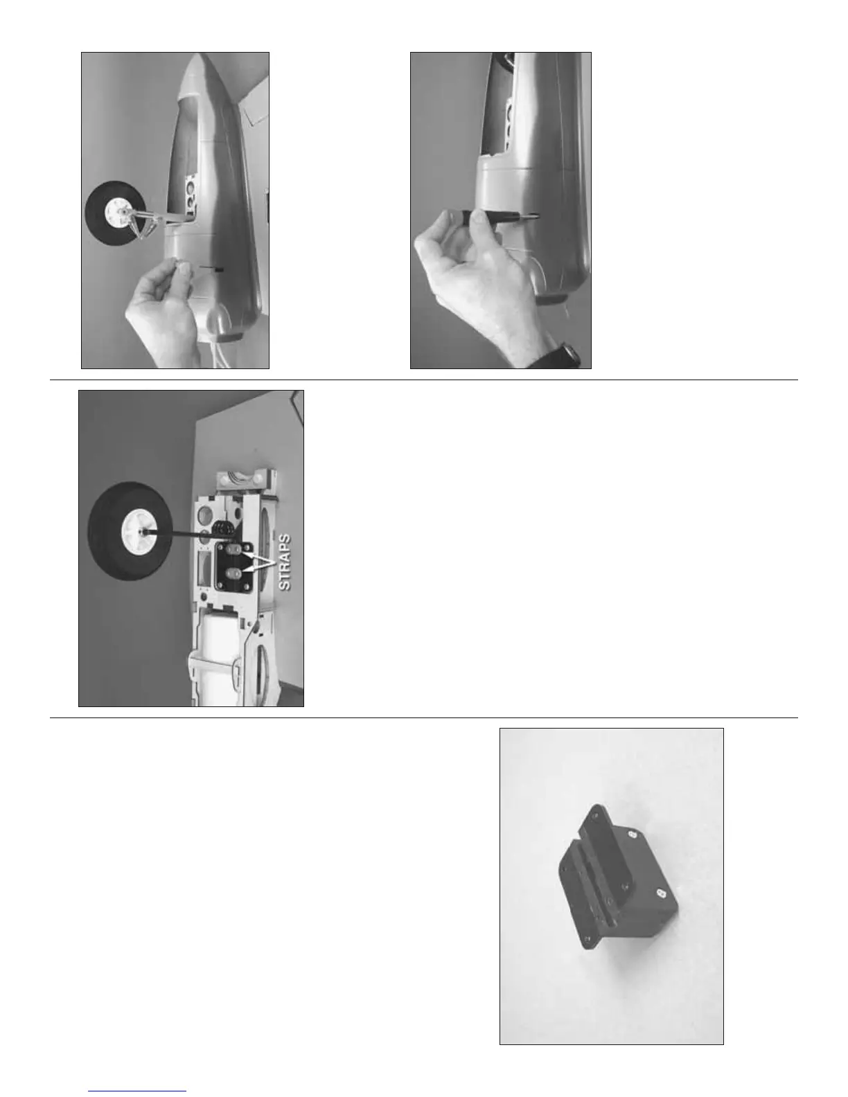
❏ ❏ 1. Assemble one of the landing gear mounts
by using eight 3 x 12mm fl at-head Phillips screws to
mount an aluminum mounting bracket to each side of
one of the molded plastic main landing gear blocks.
Refer to this photo while mounting the landing gear.
❏ ❏ 2. Center the landing gear mount on the
mounting rails. Then, drill four 7/64" [2.8mm] holes for
the mounting screws. Mount the landing gear mount
with four #6 x 1/2" [13mm] Phillips screws.
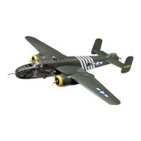
❏ ❏ 3. Mount the left, main landing gear wire into the
landing gear mount using two nylon straps and four #4
x 1/2" [13mm] screws. Mount one of the main wheels
to the landing gear wire with two 5mm wheel collars
and 6-32 set screws with threadlocker on the threads.
❏ 4. Mount the other landing gear to the right inboard
wing panel the same way. Add a drop of oil to both
sides of the wheels where they contact the collars.
MOUNT THE FIBERGLASS NACELLE COVERS
❏ ❏ 1. If you haven’t done so already, remove the left
engine from the engine mount so the nacelle cover
will fi t over the nacelle. Place the left fi berglass nacelle
cover over the nacelle on the wing. Use a pushrod
sharpened on the end or a Dead Center
™
Engine Mount
Hole Locator to mark the location of the three mounting
screws for the nacelle cover into the bottom of the wing.
❏ ❏ 2. Remove the nacelle cover. Drill 3/32" [2.4mm]
holes into the wing at the marks. Enlarge the holes
in the plywood mounting tabs in the nacelle cover
only with a 1/8" [3.2mm] drill. Use a long #1 Phillips
screwdriver to temporarily mount the nacelle cover to
the wing with four #4 x 5/8" [16mm] Phillips screws,
#4 fl at washers and #4 lock washers.
❏ ❏ 3. Remove the nacelle cover. Add a few drops
of thin CA to each of the screw holes for the nacelle
cover mounting screws. Allow the CA to harden before
mounting the nacelle cover back to the wing.