17
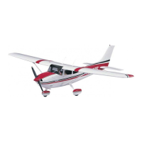
compressed air. Make sure the gear locks at both
ends—up and down. It may be necessary to slightly
trim the lever to allow the landing gear strut to move
freely. If necessary, remove the lever, trim, reinstall
and test.
❏ ❏ 10. Use coarse sandpaper to roughen the
mounting base of two small nylon control horns
(shown in the photo to the right).
3/8"
[10mm]
2-1/2"
[65mm]
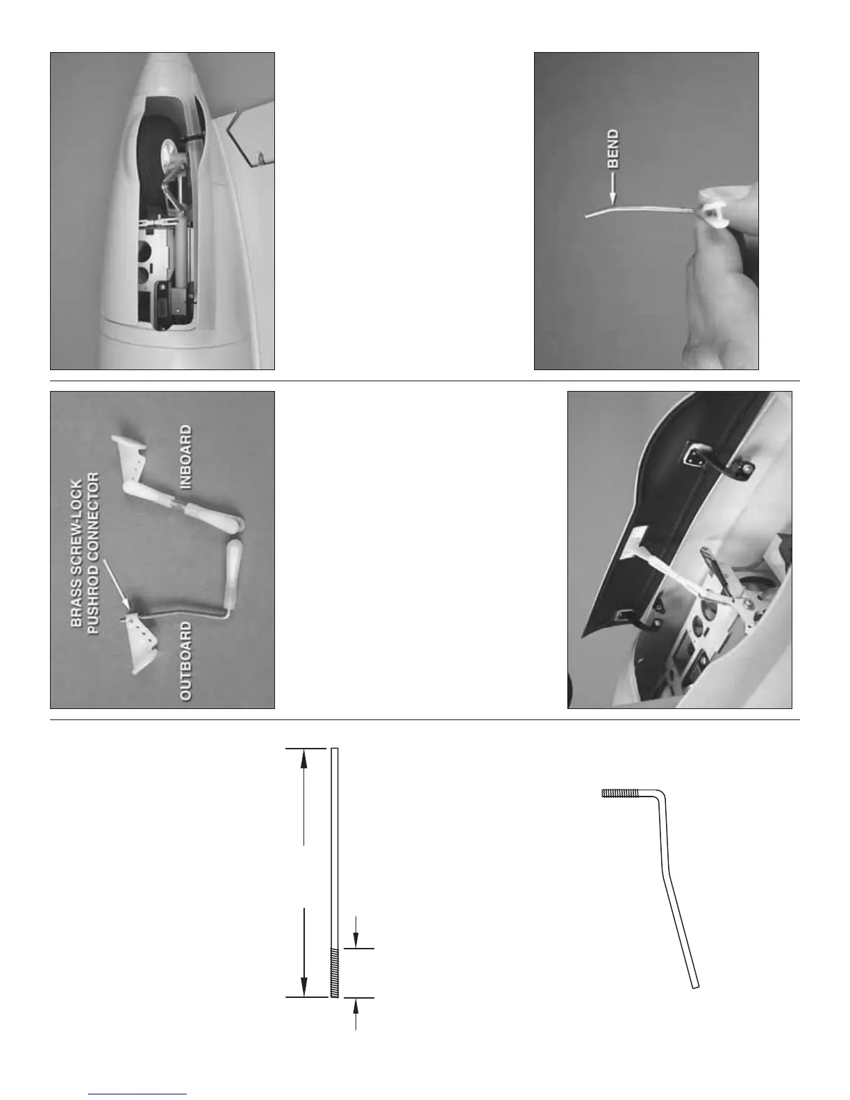
INBOARD DOOR PUSHROD
❏ ❏ 11. Make an inboard door pushrod fi rst by cutting
part of the threaded end and part of the unthreaded
end of a 4" [100mm] pushrod as shown above.
INBOARD DOOR PUSHROD
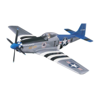
❏ ❏ 12. Use the sketch as a template to bend the
pushrod as shown.
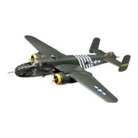
❏ ❏ 13. The same as was done on the ball links for the
door hinges, cut 1/8" [3mm] from the end of two nylon
clevises. Make the outboard door pushrod using
the short clevises and complete the inboard pushrod
using another regular clevis and the hardware shown.
Do not install the nylon retainer on the brass screw-
lock pushrod connector until instructed to do so later.
❏ ❏ 14. Connect the outboard pushrod to the
bellcrank lever. Use medium CA to glue the control
horn to the door in alignment with the lever. Retract
and extend the gear by hand, adjusting the length
of the pushrod so the door will close when the gear
is retracted. Retract and extend the gear with air
pressure, making sure it works. Make sure the rear
hinge on the outboard door isn’t rubbing against the
wheel when the door is closed. If it is, you can use
a hobby knife to carefully trim down the other side
of the wheel around the hole for the axle to shift the
wheel over, or remount the rear of the nacelle cover
slightly over to the side—either of which will give the
hinge and wheel more clearance.
❏ ❏ 15. Make one more bend in the inboard pushrod
about 1/2" [13mm] from the end as shown.