24
How to Solder
A. Use denatured alcohol or other solvent to
thoroughly clean the pushrod. If necessary, cut
the pushrod wire to the correct length. Roughen
the end of the pushrod with coarse sandpaper
where it is to be soldered.
B. Apply a few drops of soldering fl ux to the end of
the pushrod. Then, use a soldering iron or a torch
to heat it. “Tin” the heated area with silver solder
(GPMR8070) by applying the solder to the end.
The heat of the pushrod should melt the solder—
not the fl ame of the torch or soldering iron—thus
allowing the solder to fl ow. The end of the wire
should be coated with solder all the way around.
C. Place the clevis on the end of the pushrod. Add
another drop of fl ux, and then heat and add
solder. The same as before, the heat of the
parts being soldered should melt the solder,
thus allowing it to fl ow. Allow the joint to cool
naturally without disturbing. Avoid excess
blobs, but make certain the joint is thoroughly
soldered. The solder should be shiny, not rough.
If necessary, reheat the joint and allow to cool.
D. Immediately after the solder has solidifi ed, but
while it is still hot, use a cloth to quickly wipe off
the fl ux before it hardens. Important: After the
joint cools, coat with oil to prevent rust. Note:
Do not use the acid fl ux that comes with silver
solder for electrical soldering.
This is what a properly
soldered clevis looks like—
shiny solder with good fl ow,
no blobs, fl ux removed.
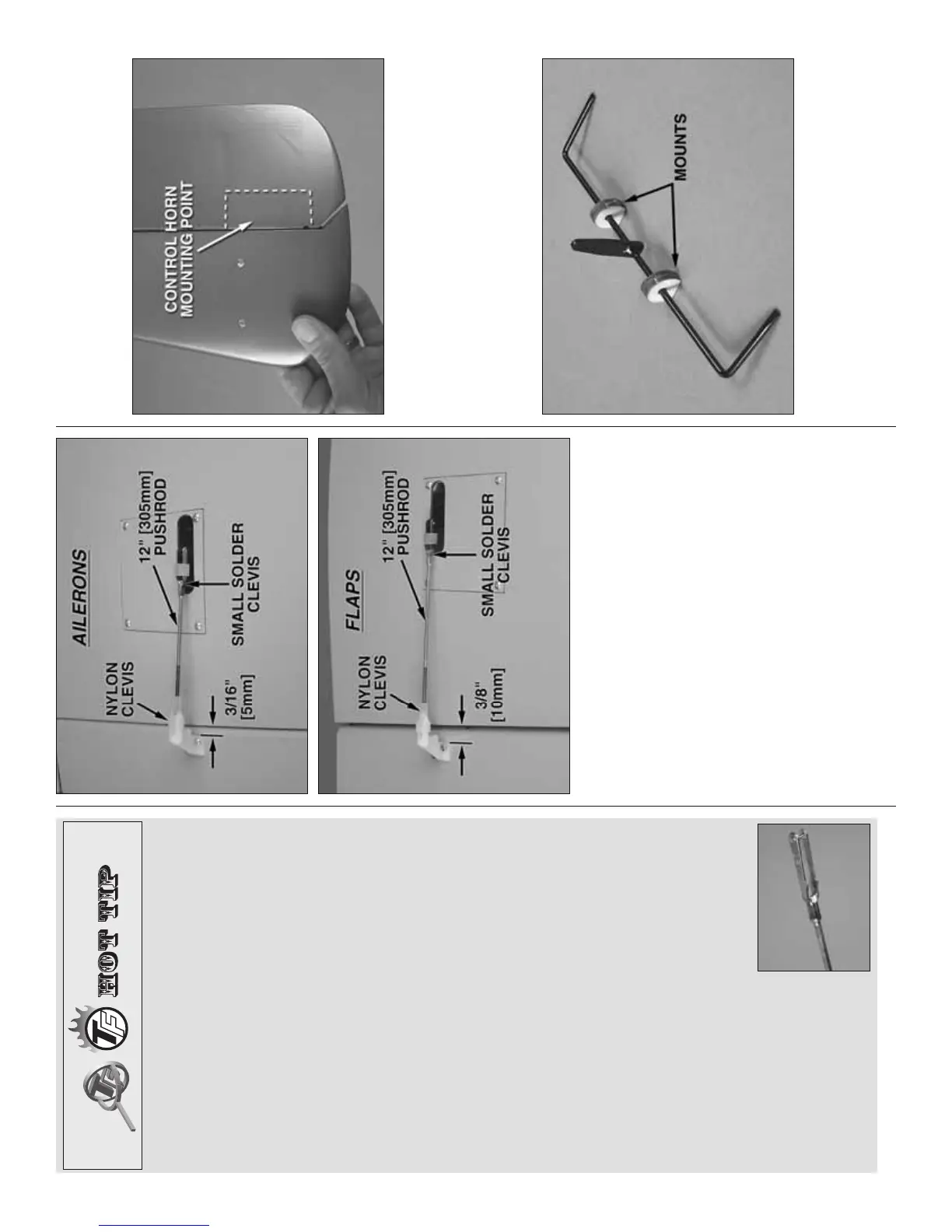
❏ 6. Hook up the fl aps and ailerons using the
hardware shown. For the fl aps, note that when the
fl aps are fully retracted (“up”) the servo arms should
be back and when the fl aps are extended the servo
arms should be forward. Also note that the front edge
of the fl ap control horns is set back 3/8" [10mm] from
the TE of the wing and the front edge of the aileron
control horns is 3/16" [5mm] from the TE of the
wing. Drill 1/16" [1.6mm] holes for the control horn
mounting screws. Mount the horns with #2 x 3/8"
[9.5mm] Phillips screws and mount the hatches with
#2 x 3/8" button-head Allen screws. After installing
all the wood screws, temporarily remove the screws,
add a few drops of thin CA to each hole, allow the CA
to harden and then reinstall all the screws.
ASSEMBLE THE TAIL
HINGE THE ELEVATORS AND RUDDERS
❏ 1. Use 30-minute epoxy to hinge the rudders to the
vertical stabilizers. Be certain the mounting points in
the rudders for mounting the control horns are on the
bottom and also make sure the rudders aren’t pushed
too close up to the vertical stabilizers. Otherwise,
control throw may be limited. Set the rudders aside
while working on the elevators.
❏ 2. Use coarse sandpaper to roughen the torque
arm portions of the elevator joiner wire so glue will
adhere. Slide two plywood elevator joiner mounts
over both ends of the elevator joiner wire. Then, glue
the two sets of mounts together.