23
the pushrods into the holes. Then, use medium CA to
glue the pushrods in.
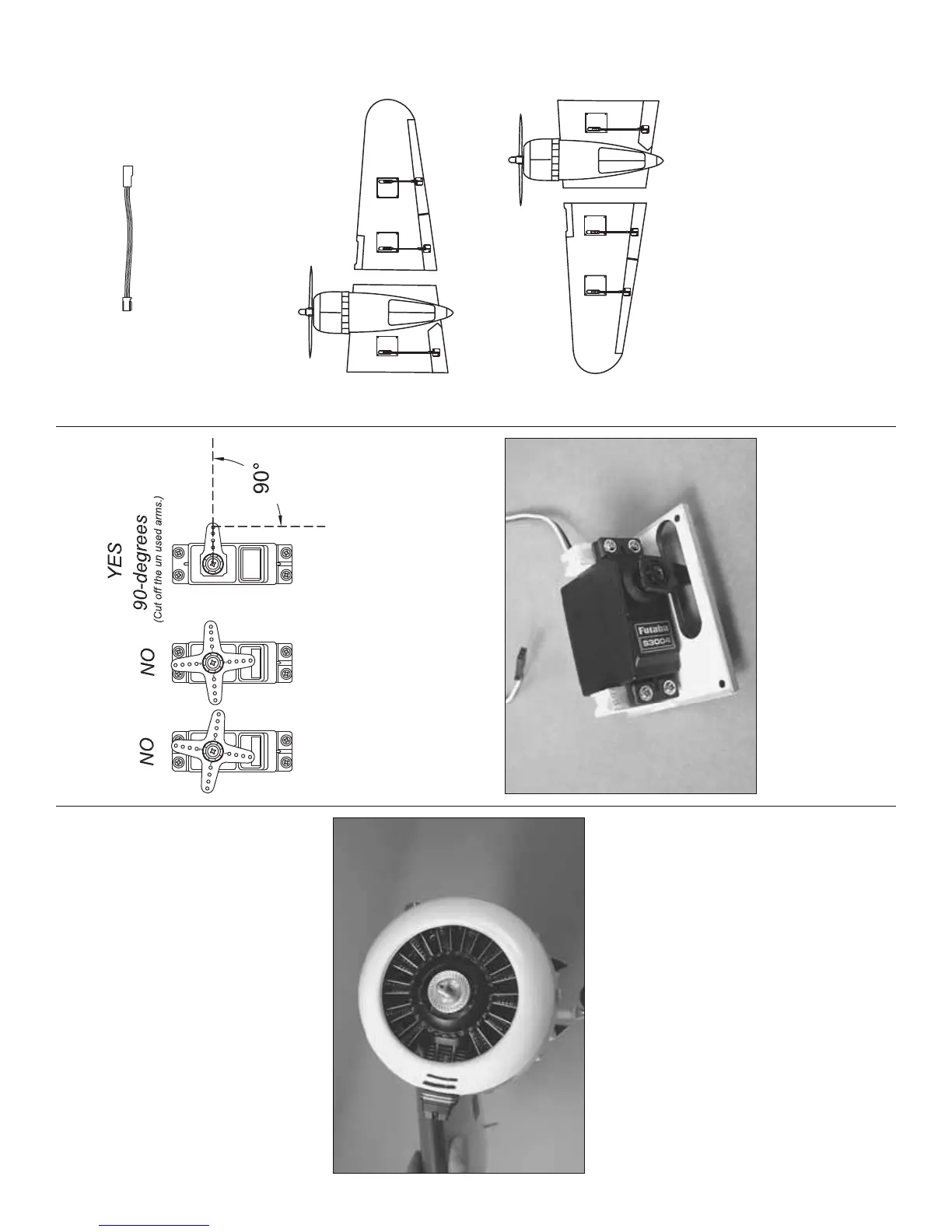
❏ ❏ 4. Fit the replica engine in the cowl and align the
two missing cylinders with the cutout for the engine.
Level the replica engine inside the front of the cowl,
double-check the alignment, and then use thin CA
to carefully glue the replica engine into position. Use
care not to use too much CA which could run onto the
outside of the cowl.
❏ ❏ 5. If necessary, cut a hole in the top of the
replica engine in alignment with the slot in the top of
the cowl for the 3/32" Allen wrench.
❏ ❏ 6. Take the drive washer off the engine. If
necessary, enlarge the hole in the front of the replica
engine so the cowl will go over the engine. Mount
the cowl to the nacelle and put the drive washer
back on. If you prefer not to remove the drive washer
for installing the cowl, the hole in the middle of the
replica engine will have to be enlarged even more.
Similarly, if you install the valve cover on the engine
after you install the cowl, the hole in the cowl for the
engine can remain small.
❏ 7. Mount the other replica engine in the other cowl
the same way.
HOOK UP THE FLAPS AND AILERONS
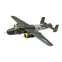
❏ 1. Retrieve your fl ap and aileron servos. Center
each servo by connecting it to the receiver, centering
the trims on the transmitter, and then turning on the
transmitter and receiver. Once you fi nd the servo arm
that’s 90-degrees, cut off the rest.
❏ 2. Mount the servos to the mounting blocks on each
of the six hatches by using the holes in the servos as
guides for drilling 1/16" [1.6mm] holes into the servo
blocks. Temporarily mount the servos with the screws
that came with them, remove the screws and servos,
and then harden each hole with a few drops of thin CA.
Allow the CA to harden. Then, remount the servos.
6" [150 mm]
SERVO EXTENSION
❏ 3. Connect a 6" [150mm] servo extension to
each aileron servo. (Refer to the “Servo Extensions”
sketches in the back of the manual for full diagrams
of what servo extensions and Y-harnesses are used.)
Same as the throttle servos, secure the connection
with 1-1/2" [40mm] pieces of heat shrink tubing.
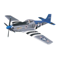
The hatches have been
enlarged for clarity.
LEFT WING
RIGHT WING
❏ 4. Noting the orientation of the servo hatches in the
bottom of the wing, place the servo hatches with the
servos in the respective wing panels—be certain the
screws that hold on the servo arms are in all the servos!
Use the strings in the wings to guide the servo wires
out the ends of the panels—or just drop them down
through the holes while holding the wings on-end.
❏ 5. Prepare for making the fl ap and aileron pushrods
by reading the following “Hot Tip” on how to solder.
Then, gather your soldering equipment.