26
❏ 4. The rudder servos move together, so they may
be linked with a Y-harness connector (rather than
using the mixing in your transmitter). Use the strings
in the stab to guide two 12" [300mm] servo extensions
through each hatch opening and out the round hole
in the bottom. Connect the rudder servos to the
extensions and secure the connections with heat
shrink tubing.
❏ 5. Temporarily mount the rudder servo hatches in
the hatch openings with #2 x 3/8" [9.5mm] button-
head Allen screws. Remove the screws and add a
drop of thin CA to each screw hole. Allow the CA to
harden and remount the hatches.
❏ 6. Connect the ends of the servo extensions
outside the stab to a Y-harness and secure those
connections with heat shrink tubing too.
❏ 7. Mount both vertical stabilizers to the horizontal
stabilizer with 4-40 x 3/8" [9.5mm] Phillips screws
and threadlocker on the threads.
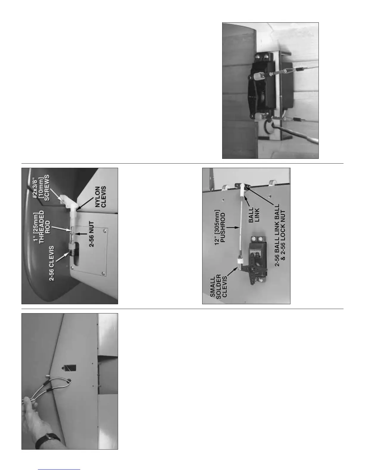
❏ 8. Connect the rudders to the rudder servos with
pushrods and the hardware shown in the photo. Don’t
forget to add thin CA to the holes in the rudder for the
wood screws.
❏ 9. Now would be a good time to center the rudders
by adjusting the length of the pushrods and setting
the control throws as shown on page 43.
…Back to the elevator servo…
❏ 10. Mount the elevator servo in the top of the
elevator—if necessary, cut a notch in the servo
opening in the bottom of the stab to accommodate
the servo wire. Connect the elevator servo to the
elevators using the hardware shown—don’t forget to
remove the servo mounting screws and harden the
screw holes with thin CA. Remount the servo.
❏ 11. Connect a 36" [910mm] servo extension to the
elevator servo and secure the connection with heat
shrink tubing.
❏ 12. Guide the servo extensions through the plastic
tube in the fuselage up to the radio compartment. If
you can’t get the extensions to go down through, you
could fi rst insert a piece of string with a weight on
the end down through the front of the tube, and then
connect the string to the extensions and pull them
back through. Mount the stab to the fuselage with two
4-40 1-1/2" [38mm] SHCS and #4 lock washers, fl at
washers and a drop of threadlocker on the threads.
Connect the elevator and rudder servos to the receiver
and operate the controls to make sure everything
works smoothly. Make any adjustments necessary.
MOUNT THE NOSE GEAR
Refer to this photo for the following four steps.
❏ 1. Temporarily connect the servo you will be using
for the nose steering to your radio and center the
servo. Cut off the two unused arms.