27
❏ 2. Connect one of the 24" [610mm] braided steel
cables to a brass coupler with a copper swage—if
you can’t get the end of the cable to go through the
swage, use a hobby knife to scrape some of the plastic
coating from the end of the cable. Tightly squeeze the
swage with pliers so the cable won’t come out.
❏ 3. Prepare another cable the same way. Connect
both cables to the nose steering servo with 2-56
metal clevises and silicone clevis retainers.
❏ 4. Mount the nose steering servo in the nose
steering servo tray down inside the fuselage—it’s
almost out of reach, but not too diffi cult to get to.
❏ 5. Guide the steering cables up through the plastic
tubes in the front of the fuselage
From this point forward steps that are for retracts
only are preceded by an “R” and steps that are
for fi xed gear only are preceded by an “F.”
If installing retracts skip the following two steps.
❏ F6. Assemble the nose gear mount by using
eight 3 x 12mm fl at head Phillips screws to attach
the aluminum mounting brackets the plastic nose
gear block. Note which side of the nose gear block is
the bottom.
❏ F7. Attach the nose gear wire to the nose gear
mount using the hardware shown and use threadlocker
on all the screws.
If installing fi xed landing gear,
skip the next six steps.
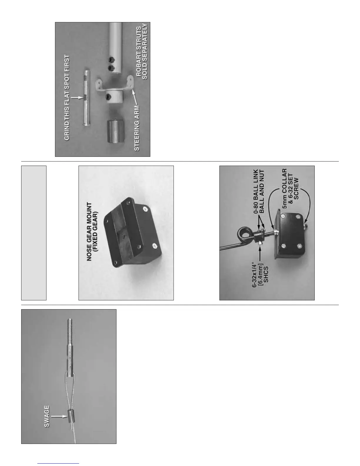
Refer to this photo for the following three steps.
❏ R8. Remove the strut assembly from the retract
unit of the retractable nose landing gear. Grind a fl at
spot in the steering shaft for the set screw in the
steering arm only. This is best done with a cutoff
wheel in a rotary tool to get the fl at spot started, and
then using a small metal fi le to square it up.
❏ R9. Reassemble the strut assembly, but do not fi t
it into the retract unit.