28
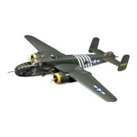
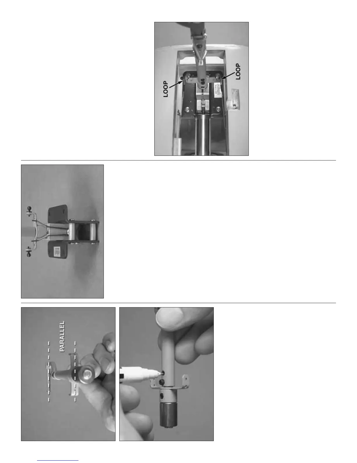
❏ R10. With the strut assembly back together but
still out of the retract unit, align the steering arm with
the axle and hold it in position with the top set screw.
Remove the bottom set screw and use a fi ne-point
felt-tip pen to mark the location of the hole. Grind
another fl at spot at the mark. Reassemble the unit
making sure the steering arm has remained parallel
with the axle. Adjust the fl at spot if necessary. When
assembling the unit for the fi nal time, use threadlocker
on the threads of all the set screws.
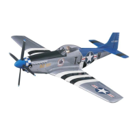
❏ R11. Reassemble the strut to the retract unit.
❏ R12. Mount an 0-80 ball link to both steering arms
with a drop of threadlocker and 0-80 nuts.
❏ R13. Connect 18" [480mm] of air line to each
fi tting on the air cylinder on the nose gear. Do not
connect the short pieces of tubing from your can of
compressed air to the air lines until step R17.
❏ R14. Holding the retract unit in your hand, retract
the gear (put the gear up). Guide the air line attached
to the side of the air cylinder through the small hole
in former F2 in the fuselage. Then, place the retract
in the mounting rails in the fuselage.
NOTE: The rest of the nose gear mounting
instructions are for both fi xed gear and
retractable gear even though retracts are shown.
Where applicable, separate notes for each setup
are provided.
❏ 15. Place the nose gear in the mounting rails in the
fuselage. Mark the locations of the screw mounting
holes onto the wood rails (for retractable nose gear
this will be easier to do if the gear is retracted). If
installing fi xed gear, temporarily remove the nose
gear. Drill four 7/64" [2.8mm] holes through the rails
at each mark. Mount the gear to the rails with four #6
x 1/2" [13mm] Phillips screws.
❏ 16. Mount the nose wheel to the gear. If using
retracts, cut the axle to the correct length and grind
or fi le a fl at spot for the set screw. If using fi xed gear
mount the nose wheel with two collars and 6-32 set
screws—and use threadlocker on all screws.
❏ R17. If mounting retractable nose gear, operate the
gear by hand and with your can of compressed air.
Make certain the gear operates freely, does not hit the
edges of the opening and is able to lock in both the up
and down positions. Make any adjustments necessary.
❏ 18. Connect the nose steering servo to your
radio and turn the system on. Make sure the servo
arm is centered. Note: A good way to set up the
nose steering is to connect the servo to an unused,
available channel in your receiver. Use the mixing in
your transmitter to electronically mix the nose steering
servo to the rudder, but assign a dial or lever on the
transmitter to the nose steering servo. At the fl ying
fi eld the dial or lever can be used to trim the nose
wheel so the model will roll straight down the runway.
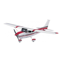
❏ 19. With the radio system on (so the nose steering
servo arm cannot move), loop the ends of the steering
cables over the ball links on the nose gear and secure
with another swage on each cable. The loops in each
cable should be large enough to slip over the ball
link, but small enough so that they won’t come off on
their own. Adjust the clevises on the servo end of the
cables to center the nose wheel.