41
certain the magnets are in the correct orientation to
attract the magnets in the antenna, press the magnets
into the holes you cut in the fuselage and glue them
into position with thin CA.
❏ 4. “Snap” the ADF football antenna into position.
Don’t forget to remove it when transporting the model.
MOUNT THE PROPELLER HUBS
This model comes with two painted, aluminum
propeller hubs with 5/16"-24 threads that fi t the O.S.
.70 four-stroke engines. If using these propeller hubs,
be certain to use threadlocker on the threads so the
hubs will not loosen if one of the engines backfi res.
Securely tighten the hubs with a round, metal bar
(such as a screwdriver shaft) through the holes in
the hubs. If using different engines that the propeller
hubs do not fi t, Harry Higley makes similar propeller
hubs with different threads that will fi t your engines.
APPLY THE DECALS
❏ 1. Use scissors or a sharp hobby knife to cut the
decals from the sheet.
❏ 2. Be certain the model is clean and free from oily
fi ngerprints and dust. Prepare a dishpan or small
bucket with a mixture of liquid dish soap and warm
water—about one teaspoon of soap per gallon of water.
Submerse the decal in the soap and water and peel off
the paper backing. Note: Even though the decals have
a “sticky-back” and are not the water transfer type,
submersing them in soap & water allows accurate
positioning and reduces air bubbles underneath.
❏ 3. Position the decal on the model where desired.
Holding the decal down, use a paper towel to wipe
most of the water away.
❏ 4. Use a piece of soft balsa or something similar
to squeegee remaining water from under the decal.
Apply the rest of the decals the same way.
GET THE MODEL READY TO FLY
BALANCE THE MODEL (C.G.)
More than any other factor, the C.G. (balance point)
can have the greatest effect on how a model fl ies,
and may determine whether or not your fi rst fl ight
will be successful. If you value this model and wish
to enjoy it for many fl ights, DO NOT OVERLOOK
THIS IMPORTANT PROCEDURE. A model that
is not properly balanced will be unstable and
possibly unfl yable.
At this stage the model should be in ready-to-fl y
condition with all of the systems in place (with the
possible exception of the receiver battery pack if you
decided to fi nd out where the model balances fi rst),
including the engines with propellers and propeller
hubs, landing gear, the complete radio system and
all the scale details that you will have in place when
you fl y the model. If using retracts, the landing gear
should be down.
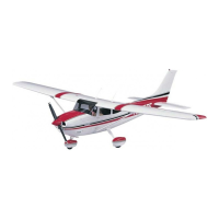
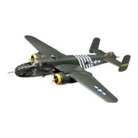
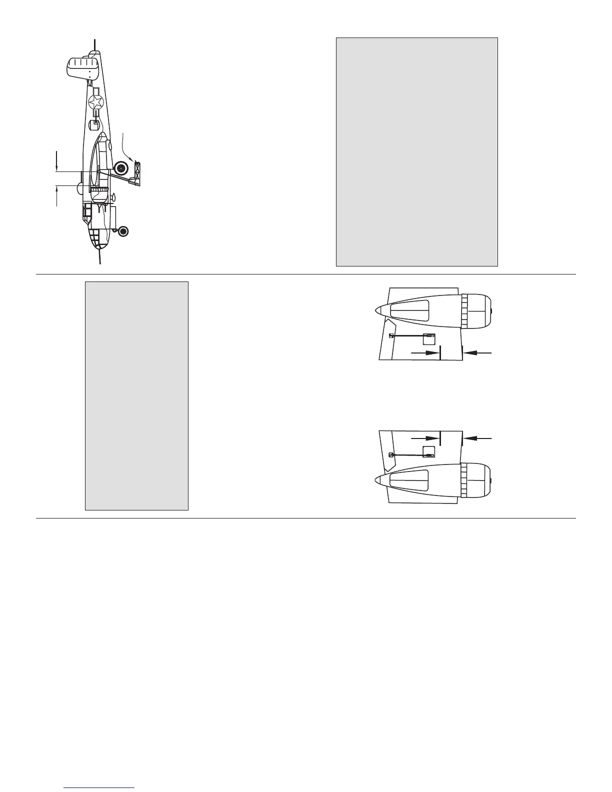
The balance point is 5" [127mm]
from the leading edge of the wing
where it contacts the fuselage.
5"
[127mm]
5" [127mm]
(For illustration purposes the supports of the C.G.
Machine are shown outboard of the engine nacelles,
but as specified in the instructions, the model should
actually be supported where the wings meet the fuselage.)
Great Planes
C.G. Machine
❏ 1. If you will be using a Great Planes C.G. Machine to
check the balance point, set the rulers to 5" [127mm].
If not using a Great Planes C.G. Machine, and if you
haven’t already done so, use a straightedge and a
fi ne-point felt-tip pen to mark the balance point on
the bottom of both inboard wing panels 5" [127mm]
back from the leading edges where they meet the
fuselage. Place 1/16" to 1/8" [1.5 to 3mm] strips of
tape over the lines you marked so you will be able to
feel the balance point with your fi ngers when lifting
the model to balance.
This is where your model should balance for the
fi rst fl ights. Later, you may wish to experiment by
shifting the C.G. up to 1/2" [13mm] forward or 1/2"
[13mm] back to change the fl ying characteristics.
Moving the C.G. forward may improve the
smoothness and stability, but the model may then
require more speed for takeoff and make it more
diffi cult to slow for landing. Moving the C.G. aft
makes the model more maneuverable, but could
also cause it to become too diffi cult to control. In
any case, start at the recommended balance
point and do not at any time balance the model
outside the specifi ed range.
❏ 2. If you haven’t yet done so, join the wings to
the fuselage with all the aluminum joiner tubes and
fasteners. If you haven’t yet mounted the receiver
battery keep it within reach so you will be able to
place it on the fuselage to fi nd out where it should be
mounted inside.
 Loading...