9
ON OFF
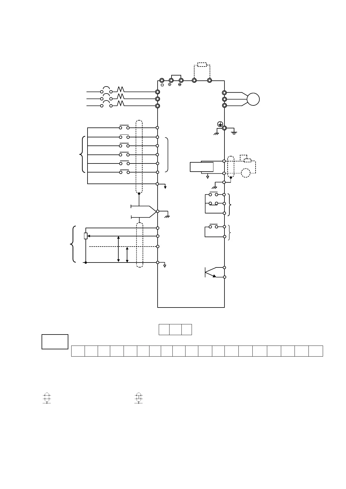
3.1 CONNECTION DIAGRAM
Below is connection diagram of the main circuit and control circuit. Using the digital operator, the
motor can be operated by wiring the main circuit only.
R
3-Phase
L1(R)
S
Power Supply
L2(S)
200 to 240V
345 to 480V
50/60 HZ
TL3(T)
MCCB
Breaking Resistor (Option)
Motor
IM
Ground (100Ω or less)
Forward Run/Stop
Reverse Run/Stop
External Fault
Fault Reset
Multi-step Speed Setting 1
Multi-step Speed Setting 2
Factory
Setting
S1 Forward Run
when CLOSED
S2
SC
S3
S4
S6
S5
Multi-function
Contact input
Sequence Commom
Terminal (0V)
G
FS
FV
FI
FC
0V
1
2
B1 B2
U(T1)
V(T2)
W(T3)
AM
AC
(G)
MA
MB
MC
M1
M2
Analog
Monitor
Shield Sheath
Connection
Terminal
Freq. Setting Power
Supply +15V 20mA
Master Freq. Ref.
0 to 10V (20kΩ)
Master Freq. Ref.
4 to 20mA (250Ω)
[0 to 10V(20kΩ)input available]
FM
-
+
Multi-function Analog Output 0
to +10V
(Output Frequency at Factory
Setting)
Multi-function Contact Output
Contact Capacity:250 VAC 1A or less
30 VDC 1A or less
(Fault Output Signal at Factory Setting)
Multi-function Contact Output
250 VAC 1A or less
30 VDC 1A or less
(Signal during Running at Factory Setting)
TG 250
TG 300
P
P
0V
4 to 20mA
0 to +10V
2kΩ
Master
Frequency
Reference
M4
M3
OPEN COLLECTOR OUTPUT
(ZERO SPEED SIGNAL)
(OPTION)
Connection Diagram
W2
S1 S2 S3 SC SC S4 S5 S6 FV FI FS FC AM AC M1 M2 MA MB MC
VR SET HZ W2 OFF
REMOTE SET HZ W2 ON
Note:
1.
indicates shielded wires and
P
indicates twisted-pair shielded wires.
2.Voltage or current input for the master frequency reference can be selected by constant H042.
Voltage reference input is preset at the factory.
3.Control circuit terminal FR of +15 V has a maximum output current capacity of 20 mA.
4.Multi-function analog output should be used for monitoring meters (e.g. output frequency meter)
and should not be used for feedback control system.
G