
R
Rachel SmithAug 13, 2025
What to do if Top TP has a bill jammed?
- SSherry ReyesAug 14, 2025
If a bill gets jammed in your Top Industrial Equipment, open the bill path unit and remove the jammed bill.
What to do if Top TP has a bill jammed?
If a bill gets jammed in your Top Industrial Equipment, open the bill path unit and remove the jammed bill.
What to do if Top TP Industrial Equipment shows stacker error or stacker full?
If your Top Industrial Equipment displays a stacker error or indicates that the stacker is full, inspect the stacker for any foreign objects and clean it. If the error persists, empty the bill box.
What to do if Top TP Industrial Equipment shows motor error?
If your Top Industrial Equipment shows a motor error, inspect the bill path for any foreign objects and clean them.
What to do if Top Industrial Equipment recognition sensor module shows error?
If the recognition sensor module on your Top Industrial Equipment is showing an error, inspect the sensor and bill path for any foreign objects and clean them.
What to do if Top TP detects a stringing attempt?
If your Top Industrial Equipment detects a stringing attempt, inspect the sensor or bill path for any foreign objects and clean them.
What to do if Top TP shows hook sensor error?
If the hook sensor on your Top Industrial Equipment is showing an error, inspect the security hook for any foreign objects and clean them.
Why is my Top TP disabled?
If your Top Industrial Equipment is disabled, check the DIP switch setting to ensure it is correct.
What to do if Top Industrial Equipment shows fish sensor error?
If the fish sensor on your Top Industrial Equipment is showing an error, inspect the sensor and bill path for any foreign objects and clean them.
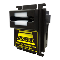
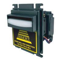
Provides a general overview of the TP series bill acceptor and its purpose.
Lists the key functional and design features of the TP series bill acceptor.
Details general specifications like acceptance rate, interface, and bill insertion type.
Outlines electrical parameters including power source and consumption.
Covers mechanical aspects like weight, dimensions, and bill width.
Lists the main unit and accessories provided in the package.
Provides detailed dimensional drawings for TP1/TP1-P5 upper bezel.
Provides detailed dimensional drawings for TP1-P8 upper bezel.
Shows dimensional drawings for TP1/TP1-P5 middle bezel.
Displays dimensional drawings for TP1-P8 middle bezel.
Provides dimensional drawings for TP2/TP2-P5 upper bezel.
Shows dimensional drawings for TP2/TP2-P5 middle bezel.
Displays dimensional drawings for TP3 and TP1-K bezels.
Details interface types and required harness connections for setup.
Explains the pinout and format for the WEL-R7U02 harness.
Details the pinout and format for the CU-R961-1 harness.
Outlines the pinout and format for the WEL-R7U06 harness.
Describes the input/output circuit logic for the Pulse interface.
Explains the input/output circuit logic for the RS232 protocol.
Details the location and purpose of DIP switches for configuration.
Provides step-by-step instructions for cleaning internal parts.
Lists LED flash codes and their corresponding corrective actions for issue resolution.
| Brand | Top |
|---|---|
| Model | TP Series |
| Category | Industrial Equipment |
| Language | English |