Do you have a question about the Topcon AT-G6 and is the answer not in the manual?
Instructions on safe handling and warnings, including protection from sun glare and injury.
Steps to properly set up the tripod for instrument stability and secure placement.
Procedure for securely mounting the auto-level instrument onto the tripod head.
Method to precisely position the instrument over a survey point using a plumb bob.
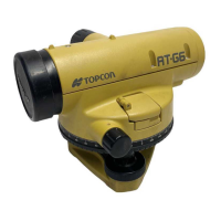
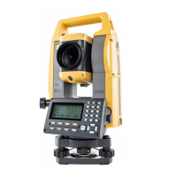
The TOPCON Auto-Level, AT-G Series (specifically AT-G4 and AT-G6 models), is a precision surveying instrument designed for leveling operations, determining differences in elevation, measuring horizontal angles, and stadia surveying. It is engineered for durability and high accuracy, making it suitable for various field conditions, including wet environments.
The primary function of the AT-G Series Auto-Level is to establish a horizontal line of sight for accurate measurement of elevations and differences between points. It achieves this through a magnetically-damped compensator, which automatically levels the line of sight, ensuring stable and precise readings even in the presence of fine vibrations. This automatic leveling action significantly speeds up the surveying process. The instrument's telescope is sealed with dry gas (nitrogen) to prevent condensation on the lens surfaces, enhancing its performance in humid or wet conditions.
For measuring horizontal angles, the instrument features a horizontal circle graduated in degrees (or gons) that allows for precise angular measurements. Stadia surveying, a convenient method for determining distances, is also possible by using the instrument's stadia hairs in conjunction with a graduated rod. The distance is calculated by multiplying the stadia interval observed on the rod by a stadia ratio of 100.
Setting up the AT-G Series Auto-Level involves several steps to ensure accuracy and stability. The instrument is designed to be mounted on tripods with a 5/8 inch diameter and 11 threads per inch tripod screw, conforming to JIS B standards. It is compatible with TOPCON Type E Aluminum Tripods, Wide-frame Wooden Tripods, and Dome Head Aluminum Tripods.
Tripod Setup: The tripod legs should be extended to a suitable length and their wing nuts tightened. The hexagonal key fastening system on the tripod head should be tightened to prevent loose legs. The tripod is then positioned over the desired point, with legs spread for stability, and the shoes firmly pressed into the ground.
Instrument Attachment: The instrument is carefully placed on the tripod head, aligning the tripod screw with the socket on the instrument's base. The tripod screw is then tightened to secure the instrument. For angle measurements or establishing a line, a plumb bob is used to ensure the instrument is set up exactly over the point. If using a dome head tripod, the instrument can be slightly loosened and moved on the tripod head while checking the circular level until the bubble is centered, then tightened.
Leveling the Instrument: Initial leveling is achieved by centering the bubble of the circular level using the three leveling screws. The two leveling screws farthest from the circular level are rotated in opposite directions to move the bubble to a line perpendicular to them. Then, the remaining leveling screw is revolved to shift the bubble to the center of the circular level. If the bubble doesn't center properly, the process should be repeated.
Adjusting the Eyepiece: Before surveying, the telescope eyepiece must be adjusted to the user's eyesight to eliminate parallax. This involves pointing the telescope towards a light source, rotating the eyepiece adjustment ring fully counter-clockwise until the cross-hairs are blurred, and then slowly rotating it clockwise until the cross-hairs appear clear and distinct. Adjustments should always stop while racking the eyepiece ring in.
Sighting and Focusing: To sight a target, the telescope is pointed in its direction, and the aiming sight is used to align the target with the triangular mark in the field of view. Focusing is then achieved by revolving the focusing knob. For precise alignment, the fine horizontal knob is used. It is crucial to check for parallax by shifting the eye left and right; if the reticule cross-hairs and target do not deviate, focusing is correct.
Leveling/Determining Differences in Elevation: The instrument is set up approximately halfway between two points. A "back sight" reading is taken on a leveling rod at the starting point, and a "foresight" reading is taken on a rod at the forward point. The difference in rod readings directly gives the difference in elevation.
Measuring Horizontal Angles: After setting up and leveling the instrument over a starting point (e.g., Point C), the telescope is sighted onto a base target (e.g., Point A), aligning it with the vertical cross-hair using the fine horizontal knob. The horizontal circle is then set to zero. Next, the telescope is sighted onto a second point (e.g., Point B), and the reading on the horizontal circle indicates the angle between Points A and B from Point C.
Stadia Surveying: The instrument is sighted onto a graduated rod, and the interval between the top and bottom stadia hairs is read. This interval, multiplied by 100, gives the distance from the instrument to the rod. If the line of sight is inclined, formulas are provided to reduce the slope distance to horizontal and vertical distances.
The AT-G Series Auto-Levels are robustly constructed and designed for minimal adjustment needs. However, proper handling and periodic checks are essential for maintaining accuracy and extending service life.
Protection: The instrument should always be protected from shock and vibrations during transport. For high-precision work, shielding the instrument and tripod from strong sunlight with an awning or umbrella is recommended.
Cleaning: After use, dust should be brushed away from all exposed surfaces, which are then wiped clean and dry. The instrument should be stored in its carrying case in a well-ventilated location. For lens cleaning, dust or dirt should first be removed with a cleaning brush or rubber-ball air blower. Then, the lens surface should be gently wiped with a soft, well-washed cotton cloth or lens cleaning tissue, using alcohol or an alcohol mixture if necessary, and wiping with ever-widening circular motions from the center outwards. The lens surface should not be rubbed. The plastic carrying case can be cleaned with neutral detergent or water, avoiding benzine, thinner, or other chemical solutions.
Adjustments: While the instruments are thoroughly inspected and adjusted before shipment, it is crucial to confirm if adjustment is truly required before attempting any.
Circular Level Adjustment: To check, the telescope is revolved 180° around its vertical axis. If the bubble moves from the center, an adjustment is needed. The circular level adjustment screw on the side towards which the bubble moved is tightened with an accessory wrench, returning the bubble by half the error. The circular level bubble is then re-centered with the three leveling screws. This process is repeated until the bubble remains centered when the instrument is revolved on its axis.
Collimation Adjustment: This involves setting up the instrument midway between two walls (approx. 50 meters apart). Identical scales are placed against both walls, and both are collimated on a horizontal line of sight, ensuring the same number is read on both scales. If readings differ, the instrument is moved 2-3 meters from one scale, and the level bubble is re-centered. The farther scale is sighted, and the horizontal cross-hair line is shifted up or down using the adjustment screws (exposed by unscrewing the eyepiece cover) until it matches the reading of the nearer scale. Adjustment screws should be loosened and tightened by equal, slight amounts to maintain tension. After adjustment, the collimation is re-checked.
Repair: Users should not attempt to dismantle the telescope or revolving parts. Any overhaul or repair should be handled by an experienced and well-equipped factory or authorized representative.
The AT-G Series Auto-Levels are designed to provide reliable and accurate performance for many years, provided they are handled and maintained according to these guidelines.
| Magnification | 30x |
|---|---|
| Weight | 1.5 kg |
| Automatic Collimation | Yes |
| Objective Lens Aperture | 45 mm |
| Shortest Focusing Distance | 0.3 m |
| Compensator Working Range | ±15' |
| Stadia Multiplication Constant | 100 |
| Stadia Addition Constant | 0 |
| Operating Temperature Range | -20°C to +50°C |
| Waterproof | IPX6 |
| Working Range | ±15' |
| Absolute Encoder | No |
| Internal Memory | No |
| Laser Pointer | No |
| Field of View | 1°30' |
| Setting Accuracy | 0.3" |