Do you have a question about the Topcon GT560 AUTOLOG and is the answer not in the manual?
Simple operation using RPM sensor for unloading start/stop.
Optional function to set weight targets for unloading with alarm/control signal.
Explains Danger, Warning, Caution symbols and their meanings.
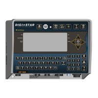
Overview of the GT560 indicator's buttons and display windows.
Displays ID, Time, Gross Weight, Print Accumulator, and Field Name.
Shows Field Name, Net Weight, ID, GPS, Moisture, Date, and Time.
Explains how to view, add, or edit field names.
How to operate in automatic mode using PTO sensor.
How to operate without AutoLog or AutoLog2.
Steps to enable Autolog2 and configure settings.
Setting up the relay function for alarms or control signals.
Procedure to check the current calibration number.
Steps to input a new calibration number.
How to change or view the setup number.
Explains different 12VDC output behaviors based on relay settings.
Indicates weight exceeds capacity limit.
Indicates weight exceeds maximum weight.
Indicates weight is less than minimum weight.
Instructions for wiring load cells to the junction box.
Verifying RPM sensor pulses for AutoLog functionality.
How to install the AutoLog sensor as a proximity switch.
| HELP MESSAGES | Context sensitive help messages in 10 languages, Long messages are scrolled |
|---|---|
| LOAD CELL EXCITATION | 8 volts D.C. Nominal, Capable of driving ten 350 Ohms transducers, Short circuit proof |
| LOAD CELL SIGNAL | Compatible with Load Cells with greater than 0.25 mv/v |
| AUTO TEMP COMPENSATION | Of internal circuitry for high accuracy weighing measurements |
| ENVIRONMENTAL ENCLOSURE | IP65, IEC 529 |
| OPERATING TEMP | -29°C to 60°C -20°F to 140°F |
| CONNECTORS | AMP plastic weather resistant circular connector. Gold plated contacts. |
| 2 REMOTE INPUTS (power/ remote ports) | Tare / Print / Hold / Net Gross / M+ / Zero / TR Hold / Re-enter Preset / Switch |
| POWER REQUIREMENTS | 10.5 to 16.0 VDC 160 mA nominal with four 350Ω L.C. |
| SETUP & CALIBRATION | Via front panel or saved when downloading the setting files. |
| GROSS RANGE | 999, 999 max-display |
| ZERO TRACKING | Selectable, On/Off |
| SPAN ACCURACY | ±(.1% + .005%/ °F) or (.1% + 0.009% °C) full scale ± 1 output count |
| MOTION DETECTION | Selectable, On/Off |
| ZERO ACCURACY | (.005%/ °F) or (0.009% °C) full scale ±1 output count for 0.5 mv/v transducer |
| WEIGH ALGORITHM | 3 internally selectable digital filters to optimize performance (General, Slow, and Fast) |
| LOW BATTERY WARNING | Enabled at 10.5V nominal |
| DISPLAY | LCD with 84 Character Display. |
| DISPLAY RESOLUTION | .01, .02, .05, .1, .2, .5, 1, 2, 5, 10, 20, 50, 100 |
| DISPLAY UPDATE RATE | Selectable: 1, 2, 3, 4 times/sec. |
| MAX. DISPLAY RESOLUTION | Adjustable to 40, 000 counts max. |
| NON-VOLATILE MEMORY | Standard |
| SIZE | 10.25” long x 8.0” high x 4” wide (260mm x 190mm x 105mm) |
|---|---|
| WEIGHT | 4.5 lbs. (2.04 Kg) |
| POUND/KILO | Selectable |