Do you have a question about the Topcon GTS-235N and is the answer not in the manual?
Important safety and handling guidelines for instrument operation and transport.
Lists critical safety warnings and precautions to prevent hazards during instrument use.
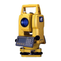
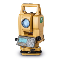
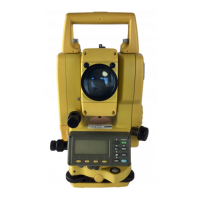
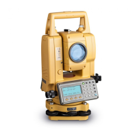
Details the names and locations of the various components of the GTS-230N series instrument.
Describes the function of each key on the instrument's control panel.
Details the functions assigned to the soft keys displayed at the bottom of the screen.
Explains the process of mounting, leveling, and centering the instrument on a tripod.
Details how tilt sensors automatically correct angle measurements for mislevelment.
Explains how to collimate targets and set the initial horizontal angle to zero.
Describes how to perform continuous distance measurements.
Describes different distance measurement modes (Fine, Tracking, Coarse) and their characteristics.
Guides users on using the instrument for stake-out operations, indicating differences from target distance.
Introduces four modes for measuring points not directly accessible, like offset points.
Details how to measure angles to a prism located at a horizontal distance.
Explains measuring distances to points offset horizontally from the prism's line of sight.
Describes measuring points on a plane where direct measurement is not feasible.
Details measuring circumscription points of a column to find its center.
Explains how to input the instrument's (occupied) coordinates to establish a reference system.
Describes the process of measuring unknown point coordinates using known instrument and prism data.
Provides access to various application programs like REM, MLM, etc.
Explains how to measure the elevation of a target point without direct line of sight.
Details measuring distances and bearings between two target prisms.
Explains how to set or calculate the Z coordinate of the occupied point.
Covers methods for calculating the area of a closed figure using coordinate data or measured points.
Explains how to measure offset points relative to a defined line.
Allows enabling or disabling the tilt correction function for angle measurements.
Guides on setting the Occupied Point and Backsight Point for measurements.
Details the procedure for staking out points along a defined road.
Explains how to select or create a file to store collected data.
Explains how to set the occupied and backsight points within the data collection mode.
Provides a step-by-step guide for performing data collection measurements.
Introduces modes for collecting offset measurement data.
Details the process for collecting angle offset measurement data.
Explains collecting distance offset measurement data with input offsets.
Describes collecting plane offset measurement data by measuring points on a plane.
Explains how to set the occupied point for layout operations, either from data or direct input.
Explains how to set the backsight point for layout operations using different methods.
Guides users on how to perform layout operations using recalled or input points.
Covers methods for establishing new points when existing control points are not visible.
Explains how to check and adjust the instrument's constant for accurate distance measurements.
Details the process for adjusting systematic errors like collimation and axis errors.
| Brand | Topcon |
|---|---|
| Model | GTS-235N |
| Category | Measuring Instruments |
| Language | English |