Do you have a question about the Topcon GTS-230 Series and is the answer not in the manual?
Guidelines for safely handling the instrument to ensure correct performance and longevity.
Explanation of warning symbols and their meaning to promote safe product usage.
Important safety warnings and precautions to prevent injury or damage during operation.
Information regarding the user's qualifications and required protective equipment.
Manufacturer's disclaimer regarding misuse, damage, or losses incurred during product operation.
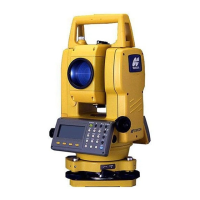
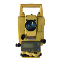
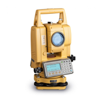
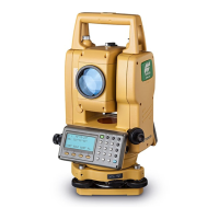
Identification and labeling of the instrument's various parts and components.
Detailed explanation of the instrument's display screen, including modes and display marks.
Description of the function of each key on the instrument's control panel.
Explanation of soft key functions displayed at the bottom of the screen for various modes.
Details on accessing and using the star key mode for instrument options and settings.
Information on connecting the instrument to a computer or data collector via RS-232C.
Instructions for connecting the instrument to power sources, including onboard and external batteries.
Step-by-step guide for setting up the instrument on a tripod, including leveling and centering.
Procedure for turning on the instrument after proper setup and leveling.
Explanation of the battery power indicator and its meaning for operation.
Information on automatic tilt correction for vertical and horizontal angles.
Guide on inputting alphanumeric characters for various instrument settings and data entry.
Procedure for measuring horizontal and vertical angles accurately.
Instructions on how to switch between horizontal angle right (HR) and left (HL) modes.
Methods for setting and measuring angles based on a required horizontal angle.
How to use the instrument in vertical angle percent grade mode.
Procedure for performing angle measurements multiple times for increased accuracy.
Setting up a buzzer sound for horizontal angle measurements at 90° increments.
Display and usage of vertical angle readings in compass mode.
Procedure for setting atmospheric correction values based on temperature and pressure.
Instructions on setting the prism constant value for accurate distance measurements.
How to perform continuous distance measurements.
Performing distance measurements multiple times or a single measurement.
Selecting different measurement modes (Fine, Tracking, Coarse) for distance measurement.
Guidance on using the stake out function to mark points in the field.
Overview of offset measurement modes: Angle, Distance, Plane, and Column.
Setting the instrument's occupied point coordinates to establish a reference system.
Procedure for setting the instrument height for accurate coordinate calculations.
Procedure for setting the target prism height for accurate coordinate calculations.
Steps for measuring coordinates of unknown points using instrument and prism heights.
Accessing and using special measurement programs like REM, MLM, and Z Coordinate.
Procedure for setting the grid factor for coordinate calculations.
Adjusting display brightness and reticle illumination levels.
Configuring various instrument settings including minimum reading, power off, and tilt correction.
Adjusting the contrast level of the instrument's LCD display.
Steps required before data collection, including file selection.
Detailed steps for executing the data collection process.
Using offset measurement modes within data collection for specific scenarios.
Automatic calculation and storage of coordinates using grid factor.
Adding or editing PCODE data entries in the instrument's library.
Configuring parameters for data collection, such as distance mode and data confirmation.
Steps for preparing the layout mode, including setting grid factor and selecting files.
Procedure for executing a layout by recalling points or inputting coordinates.
Methods for establishing new points when existing control points are not visible.
Checking the status of the internal memory, including stored data and capacity.
Methods for searching recorded data files by type and point number.
Managing files by renaming, searching within files, or deleting files.
Directly inputting coordinate data for layout or control points via keyboard.
Erasing specific coordinate data entries from a file within internal memory.
Adding or modifying PCODE entries in the library for data collection.
Transferring data between the instrument and a computer, including sending and loading.
Resetting the instrument's internal memory to its factory default state.
Formulas and examples for calculating atmospheric correction values.
Procedure for inputting temperature and pressure values to set atmospheric correction.
Formulas used for distance calculation including refraction and earth curvature corrections.
Instructions for removing, charging, and refreshing the onboard battery pack.
Overview of available modes and their selectable items for instrument configuration.
Step-by-step guide for setting various instrument modes and parameters.
Procedure to measure and adjust the instrument constant for measurement accuracy.
Steps to check if the EDM and theodolite optical axes are aligned.
Procedures for checking and adjusting theodolite functions like plate and circular levels.
Setting the instrument constant value obtained from checks and adjustments.
Adjusting systematic errors for collimation and axes compensation.
Utilizing a reference frequency check mode for EDM frequency testing.
Explanation of dual axis compensation and its effect on horizontal angle measurement accuracy.
Guidelines for charging and storing batteries to maintain capacity and service life.
| Telescope Magnification | 30x |
|---|---|
| Distance Measurement Range (Prism) | Up to 3, 000m |
| Distance Measurement Range (with prism) | Up to 3, 000m |
| Operating Temperature Range | -20°C to +50°C |
| Angle Accuracy | 5" |
| Distance Accuracy (Prism) | +/- (2mm + 2ppm) m.s.e. |
| Display | LCD |
| Communication | RS-232C |
| Angle Measurement Accuracy | 5" |
| Distance Measurement Accuracy | +/- (2mm + 2ppm) m.s.e. |