Do you have a question about the Topcon GPT-3000 Series and is the answer not in the manual?
Instrument is not waterproof; avoid submersion.
Guidelines for stable instrument setup on a tripod.
Proper installation and maintenance of the tribrach for accuracy.
Protecting the instrument from damage during transport.
Proper method for carrying the instrument.
Avoiding damage from prolonged exposure to extreme heat.
Acclimating the instrument to ambient temperature after temperature changes.
Confirming battery level before operation.
Procedure for safely removing the battery.
Normal operating sounds from the EDM motor.
Indicates immediate danger leading to death or serious injury.
Indicates potential personal injury or physical damage.
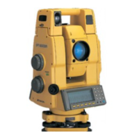
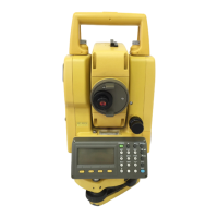
Identifies the main parts of the instrument.
Explains the instrument's display screen and its elements.
Details the function of each key on the instrument's control panel.
Describes the functions assigned to the soft keys in different modes.
Explains how to access and use the instrument's option menu via the star key.
Details the connection and data output via the RS-232C port.
Instructions for connecting external battery packs for power.
Detailed steps for leveling and centering the instrument on a tripod.
Procedure for powering on the instrument after leveling.
How to interpret the battery status indicator on the display.
Explains the automatic tilt correction feature for angle measurements.
Guide to inputting text and numbers using the instrument's keypad.
Describes the Point Guide feature for stake-out work assistance.
Instructions for turning the laser plummet feature on and off.
Step-by-step process for measuring horizontal and vertical angles.
How to toggle between right and left horizontal angle measurement modes.
Methods for setting and measuring angles based on specific horizontal values.
Method to hold and set a specific horizontal angle value.
How to input a horizontal angle directly using the instrument keys.
Explains how to display vertical angles as percentage grades.
Procedure for measuring angles multiple times to improve accuracy.
Configuration for audible alerts at 90-degree horizontal angle intervals.
How vertical angles are displayed in compass mode.
Explanation of measurement modes for prisms and non-prism targets.
How to input atmospheric conditions for correction.
Setting prism and non-prism constant values for accurate measurements.
Performing continuous distance measurements.
Measuring distances multiple times or as a single shot.
Explains different distance measurement modes (Fine, Tracking, Coarse).
Function for laying out points based on specified distances.
Overview of the four offset measurement modes.
Measures offsets using angle data.
Measures distances to offset points.
Measures points on a plane for coordinate calculation.
Measures points to determine a column's center.
Detailed procedure for angle offset measurement.
Procedure for measuring distances with an offset.
Steps for measuring points on a plane to determine its properties.
Steps to measure points on a column to find its center.
How to input the instrument's position and orientation coordinates.
Procedure to set the instrument's height for accurate measurements.
How to input the height of the prism or target.
Steps to perform coordinate measurements after setting parameters.
Accessing various measurement programs like REM, MLM.
Method to measure the elevation of inaccessible points using prism.
Calculating distances and angles between two targets.
Setting the vertical coordinate for the occupied point.
Calculating the area of a closed figure using measured points or coordinate files.
Measuring the offset and coordinate data relative to a defined line.
Adjusting the grid factor for coordinate system transformations.
Adjusting display brightness and reticle illumination levels.
Accessing various instrument settings like minimum reading and auto power off.
Selecting display units for angle and distance measurements.
Configuring the automatic power-off function to save battery.
Enabling or disabling automatic tilt correction for angle measurements.
Correcting systematic errors in angle measurements.
Specifying the type of battery for accurate power monitoring.
Controlling the heater for the display units.
Configuring communication parameters for connecting to external devices.
Adjusting the contrast level of the instrument's LCD display.
Initial setup steps before starting data collection.
Steps to select or create a file for storing collected data.
How to choose a coordinate file for use in data collection.
Setting the instrument's occupied point and backsight direction.
How to search for recorded data within the data collection mode.
Inputting PCODE/ID values using the PCODE library.
Selecting PCODE/ID entries from a predefined list.
Using offset measurement modes within data collection.
Measuring offsets using angle data.
Measuring offsets using distance data.
Measuring points on a plane for offset calculations.
Measuring points to determine column dimensions and center.
Automatic calculation and storage of North, East, Zenith coordinates.
Measuring offsets relative to a defined line.
Steps to activate the point-to-line measurement mode.
Modifying the PCODE library for data entry.
Configuring settings for the data collection process.
Initial setup steps before performing layout tasks.
Adjusting the grid factor for coordinate system transformations.
Choosing a coordinate file to use for layout operations.
Defining the instrument's location and orientation for layout.
Setting the backsight point for orientation in layout.
Procedures for performing layout tasks using stored data.
Performing layout based on coordinate data relative to a line.
Methods for establishing new points during layout.
Measuring new points using the side shot method.
Calculating the instrument's position using known points and measurements.
Checking the status and capacity of the instrument's internal memory.
Overview of methods for searching recorded data.
Searching for measured data by point number or file name.
Searching for coordinate data by point number or file.
Searching for PCODE library entries by number.
Managing files in internal memory (rename, search, delete).
Steps to rename an existing file in internal memory.
How to search for data within a specific file.
Procedure for erasing a file from the internal memory.
Manually inputting coordinate data directly from the keyboard.
Steps for entering NEZ or PTL coordinate data.
Inputting point-to-line coordinate data via keyboard.
Erasing specific coordinate data entries from a file.
Modifying entries within the PCODE library.
Managing data transfer between the instrument and a computer.
Procedures for sending measured or coordinate data to a computer.
Loading coordinate or PCODE data files from a computer.
Configuring communication settings like baud rate and protocol.
Resetting the internal memory to its default state.
Explains the formulas used to calculate atmospheric correction.
How to input temperature and pressure to set atmospheric correction.
Details the formula for distance calculation considering refraction and earth curvature.
Information on removing, charging, and refreshing the BT-52QA battery.
Lists and describes the available selection modes for instrument settings.
Step-by-step guide to configure various instrument settings.
Procedure to check and adjust instrument constants for prism and non-prism modes.
Optical axis verification for instrument components.
Steps to verify the alignment of EDM and theodolite optical axes.
Verifying the alignment of the laser pointer's optical axis with the telescope.
General guidelines and notes for adjusting theodolite functions.
Procedure to check and adjust the plate level's perpendicularity.
Procedure to check and adjust the circular level's perpendicularity.
Steps to adjust the vertical cross-hair for accurate measurements.
Process to ensure the telescope's line of sight is perpendicular to the horizontal axis.
How to align the optical plummet telescope with the vertical axis.
Steps to align the laser plummet with the measuring point.
Procedure to set the vertical angle zero datum for accurate measurements.
Instructions for inputting instrument constants for prism and non-prism modes.
Correcting systematic errors in instrument measurements.
Checking the alignment between the EDM and telescope axes.
Explains the principle and benefits of dual axis tilt compensation.
Guidelines for proper battery charging and storage to maintain performance.
| Category | Measuring Instruments |
|---|---|
| Telescope Magnification | 30x |
| Type | Total Station |
| Model | GPT-3000 Series |
| Distance Measurement Range (Prism) | 3, 000m |
| Display | LCD |
| Operating Temperature | -20°C to +50°C |