Do you have a question about the Topcon GPT-8005A and is the answer not in the manual?
Guidelines for safely handling and operating the instrument.
Icons and their meanings for safe operation.
Lists critical warnings and cautions for safe instrument use.
Groups specific warnings about fire, shock, eye injury, and battery hazards.
Covers laser radiation hazards and safe operating practices.
Specifies professional use and protective gear requirements.
Manufacturer's disclaimer regarding misuse and damages.
Safety information for invisible laser used in distance measurement.
Safety information for visible laser used in auto-tracking.
Describes importance of laser safety labels and their replacement.
Details laser safety labels for plummet models.
Indicates the status of the laser when it is emitting.
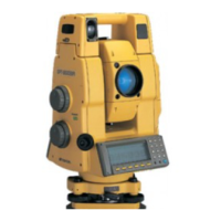
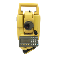
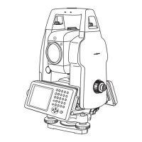
Identifies and labels the instrument's parts and features.
Describes the instrument's display layout and elements.
Covers contrast adjustment and automatic heater function.
Illustrates display content in angle and distance measurement modes.
Symbols indicating auto-tracking and auto-collimating status.
Details the function of each operating key on the instrument.
Describes how soft key functions change based on the measurement mode.
Lists options available via the star key across three screens.
Automatic power off feature to conserve battery life.
Describes outputting measured data to external devices.
Explains manual and automatic rotation methods.
Rotating to a required horizontal and vertical angle by key input.
Labels to prevent accidental pinching during automatic rotation.
Enables optical communication with RC-2II for one-man surveying.
Allows easy rotation to RC-2II side for surveying efficiency.
Commands for PC control of tracking and auto-collimating functions.
Guides on connecting internal and external battery packs.
Detailed steps for precise instrument leveling and centering.
Checks internal communication and tilt sensor offset.
Procedure for setting a password to secure the instrument.
Provides information on factors affecting battery life and indicator behavior.
Modes for configuring measurement, display, and communication.
Used for checking and adjusting instrument errors.
Covers standard measurement and application program modes.
Automatic correction for mislevelment using tilt sensors.
Enables/disables tilt correction using soft keys.
Lists systematic errors correctable by software.
Memorizes last display/mode when power is off.
Instructions for entering alphanumeric data via the keyboard.
Step-by-step guide for inserting a memory card.
Step-by-step guide for extracting a memory card.
Diagrams illustrating error due to prism misalignment.
Graphs showing distance/angle errors for prism type 2.
Graphs showing distance/angle errors for prism types 3/5.
Provides an example calculation for distance and angle error.
Groups WARNING and CAUTION notices regarding laser beam safety.
Procedure for measuring moving targets in auto-tracking mode.
Describes symbol marks for tracking, waiting, and searching states.
Indicates when the prism is not found during auto-collimation.
Illustrates the laser range and field of view for auto-tracking.
Lists items to configure for auto-tracking function.
Explains the two available search patterns for finding the prism.
Details on setting search range considering environmental factors.
Configures time before searching starts after prism loss.
Explains SURVEY vs. MACHINE CONTROL tracking speeds.
Choosing reflector type for improved tracking accuracy.
Step-by-step guide for setting tracking speed to Machine Control.
Procedures for measuring horizontal and vertical angles.
How to switch between Horizontal Right (HR) and Left (HL) modes.
Steps for measuring from a pre-set horizontal angle.
Manually setting a specific horizontal angle using the keypad.
Displays vertical angle readings as a percent grade.
Rotating the instrument to a specified horizontal and vertical angle.
Selecting between prism and non-prism measurement modes.
Setting atmospheric and prism constant corrections.
Procedure for performing continuous distance measurements.
Setting number of measurements for averaging distance.
Selecting measurement mode like Horizontal distance.
Details fine, coarse (1mm), and coarse (10mm) measurement modes.
Guides the rod person on movement for stake out.
Setting the instrument's position coordinates (NEZ).
Setting instrument and prism heights for elevation calculation.
Explains how unknown point coordinates are calculated and displayed.
Procedure for transferring measurement data to a Data Collector.
Describes the data output format for different measurement modes.
Lists available measurement application programs.
Program for setting a horizontal angle.
Program for storing and recalling coordinates.
Program for measuring distances between multiple prisms.
Setting direction angle using instrument and backsight coordinates.
Steps for storing instrument point and recalling coordinates.
Procedure for REM measurement with prism height input.
Procedure for REM measurement without prism height input.
Describes the two modes for MLM measurement.
Describes how to obtain line height measurements.
Lists the four types of offset measurement modes.
Explains how to output offset measurement results to external devices.
Angle offset for measuring prisms in hard-to-reach locations.
Procedure for measuring offset horizontal distances.
Measures edges of planes where direct measurement is impossible.
Calculates column center using circumscription points.
Procedure to start the AP-L1A communication program.
Guides setting up communication parameters.
Details on setting parameters for RS-232C communication.
Provides an overview of memory management options.
Displays internal and card memory size and status.
Procedure to protect files from deletion.
Instructions for renaming files in memory.
Steps for deleting files from internal or card memory.
Procedure for copying files between memory locations.
Erases all files from memory; files cannot be retrieved.
Used for setting Baud rate, receiving, and sending files.
Procedure for setting the communication protocol.
Receiving data files from a PC into internal memory.
Sending files from memory to a PC.
Describes the different parameter setting modes available.
Lists configurable parameters for measurement and display.
Settings for angle units and minimum display angle.
Options for tilt sensor and error correction.
Settings for vertical angle reference and angle memory.
Settings for automatic rotation and collimation accuracy.
Settings for distance units and conversion factors.
Settings for minimum distance display and audio tone.
Settings for refraction correction and coordinate storage.
Settings for coordinate format and atmospheric units.
Settings for locking angle/units and date format.
Settings for auto power off and display heater.
Settings for EDM wait time and laser plummet auto-off.
Introduces communication parameter settings.
Settings for communication baud rate and data length.
Settings for parity bit and stop bit.
Configuration settings for the RC-2H remote controller.
Detailed settings for measurement and display options.
Communication parameter settings for RS232C and RC.
Steps to set a password for instrument security.
Procedure to disable the password protection feature.
Steps to change the existing instrument password.
Procedures for checking and adjusting instrument constants.
Procedure to check non-prism mode accuracy after constant reset.
Steps to check the alignment of the optical axis.
Procedure for confirming horizontal axis alignment.
Procedure for confirming vertical axis alignment.
General guidelines for performing instrument adjustments.
Importance of firm tribrach installation for measurement precision.
Checking and adjusting the plate level.
Checking and adjusting the circular level.
Checking and adjusting the vertical cross-hair.
Procedures for checking and adjusting instrument collimation.
Checking and adjusting the optical plummet telescope.
Checking and adjusting the laser plummet.
Software compensation for systematic instrument errors.
Procedure to switch compensation features ON or OFF.
Steps to set the instrument's date and time.
Setting the constant value for prism and non-prism modes.
Checking and adjusting optic axis for auto-tracking.
Setting the prism constant value in STAR key mode.
Confirming non-prism constant is set to zero for walls.
Corrects for temperature/pressure; values retained after power off.
Provides formulas for calculating atmospheric correction.
Setting temperature and pressure values for correction.
Example of setting temp/pressure to determine PPM value.
Chart to find atmospheric correction value based on temp/pressure.
Formula for calculating distance with refraction/curvature corrections.
Details on BT-56Q battery removal, charging, and refresh.
Steps for removing and installing the battery.
Step-by-step instructions for charging the battery.
Procedure to refresh the battery to restore capacity.
Important precautions for battery charging and storage.
Steps to detach the instrument from the tribrach.
Steps to attach the instrument to the tribrach.
Securing the tribrach fixing lever to prevent accidental movement.
Overview of the BT-56Q rechargeable battery system.
Overview of external battery pack options.
Diagrams showing charging times for various battery/charger combinations.
Shows various prism arrangements and accessories.
Guidelines for safe transport and handling.
Precautions for temperature, sunlight, and cleaning.
Warnings against self-disassembly and consulting dealers.
Table of error codes, descriptions, and countermeasures.
Error for depleted memory backup battery.
Errors related to angle measurement system abnormalities.
Errors related to EDM system and internal memory.
Lists RC-2II, Tribrach TR-5, and TR-5P.
Includes Trough compass, Diagonal eyepiece, Solar filter/reticle.
Details on prism unit cases for different prism quantities.
Lists battery chargers and large capacity packs.
Includes large capacity battery pack and auto converter.
Describes tripods and data card specifications.
Provides specifications for the instrument's telescope.
Specifications for auto-tracking and auto-collimation.
Specifications for manual instrument driving.
Distance ranges for various prism types and reflector tape.
Measurement ranges for non-prism and prism modes.
Accuracy specifications for non-prism and prism modes.
Details least count and measurement times for modes.
Ranges for atmospheric, prism constant, and ambient temperature.
Specifications for electronic angle measurement.
Specifications for tilt correction method and range.
Specifications for optical plummet and laser plummet.
Specifications for physical size, weight, and durability.
Specifications for the instrument's computer unit.
Specifications for the BT-56Q rechargeable battery.
Specifications for the battery charger BC-27BR/BC-27CR.
Explanation of dual axis compensation and its benefits.
How vertical axis inclination affects horizontal angle measurements.
Formula and example for calculating horizontal angle error.
Table showing error vs. tilt and elevation.
Necessity of keeping compensators properly adjusted.
Ensuring proper horizontal angle correction via vertical indexing.
Effects of ambient temperature on recharging efficiency.
Effects of temperature on battery discharge characteristics.
Impact of storage period and temperature on battery capacity.
Emphasis on reading the license agreement before using the software.
Defines the legal agreement for using the Microsoft SOFTWARE.
Details the limited warranty and customer remedies.
Covers liability limitations and governing law.
| Type | Total Station |
|---|---|
| Model | GPT-8005A |
| Angle Accuracy | 5" |
| Distance Accuracy (Prism) | 2 mm + 2 ppm |
| Waterproof/Dustproof | IP66 |
| Measuring Range (Single Prism) | 5, 000m |
| Display | LCD |
| Data Storage | Internal memory |
| Communication | Bluetooth, RS-232C |