Do you have a question about the Topcon GPT-8001A and is the answer not in the manual?
General guidance on handling the instrument safely and correctly to ensure performance.
Proper procedure for storing the instrument in its case to prevent damage.
Recommends grease changes for driving parts every 4,000-5,000 hours.
Explains the meaning of display symbols and icons for safe operation.
Lists warnings and cautions for safe use, covering fire, electric shock, and personal injury risks.
Specifies that the product is for professional use by qualified surveyors.
Outlines the manufacturer's limitations of responsibility for product misuse or damage.
Explains laser beam usage, classification, and safety standards for GPT-8000A/8000 series.
Details the use of visible laser beam for plumb function and safety standards.
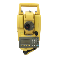
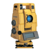
Diagrams and labels identifying the external parts of the instrument.
Details the instrument's display layout, indicators, and features like the heater.
Explains the function of each key on the instrument's keypad.
Details the functions of soft keys based on the measurement mode displayed.
Describes how to access and navigate instrument options using the star key.
Explains the auto power off feature and its setting range.
Describes options for outputting measured data to external devices.
Explains manual and automatic rotation methods for the instrument.
Explains how to use the RC-2II remote control for one-man surveying.
Lists commands for PC communication and auto-tracking/collimating control.
Details how to connect internal and external battery packs for power.
Step-by-step guide for mounting, leveling, and centering the instrument on a tripod.
Describes the power-on sequence, self-check, and password options.
Explains the battery level indicator and its meaning for measurement possibility.
Overview of main menu icons and their corresponding modes and functions.
Explains automatic tilt correction for vertical and horizontal angles.
Lists systematic errors that can be compensated by software.
Guides on entering alphanumeric characters for file renaming or data input.
Instructions on how to insert and extract a memory card from the instrument.
Explains prism alignment, potential errors due to inclination, and compensation.
Details how to perform measurements using the automatic tracking mode.
Describes the automatic collimation function for centering the prism.
Explains the laser range and field of view for auto-tracking and auto-collimating.
Details setting items for auto-tracking, including search pattern and speed.
Explains how to perform standard angle measurements.
Guides on setting and holding a required horizontal angle for measurement.
Explains how to display and use vertical angle as percent grade.
Describes how to automatically rotate the instrument to specified angles.
Explains prism and non-prism distance measurement modes.
Guides on setting atmospheric correction based on temperature and pressure.
Details setting prism and non-prism constants for accurate measurements.
Explains continuous distance measurement and display indicators.
Describes setting the number of times for measurement and averaging.
Details fine and coarse measurement modes and their applications.
Explains the stake out function for measuring distances to reach a target point.
Guides on setting occupied point coordinates (NEZ) for calculations.
Explains how to set instrument and prism heights for elevation calculations.
Describes how to execute coordinate measurement after setting heights and points.
Explains how measurement data is output to a data collector.
Lists various application measurement programs available.
Guides on setting a direction angle for backsight orientation using coordinates.
Explains how to retain coordinates when the instrument is moved.
Describes the REM procedure to measure elevation when prism placement is difficult.
Explains MLM for measuring distances and elevations between prisms.
Explains the LINE mode for obtaining line height.
Introduces the four offset measurement modes.
Details the Angle Offset measurement mode.
Explains distance offset measurement by inputting horizontal offset.
Explains Plane Offset measurement for edges of planes.
Explains Column Offset measurement for finding column center.
Explains using compatible communication programs like AP-L1A.
Guides on starting and setting up the AP-L1A communication program.
Details setting communication courses and parameters for RS232C.
Guides on executing and stopping communication.
Explains how to view memory size, free memory, and battery expiration.
Details the procedure for protecting files from deletion.
Guides on renaming files in internal or card memory.
Explains how to delete files from memory, noting protection status.
Details copying files between internal memory and card memory.
Describes how to initialize memory, erasing all files.
Guides on setting communication protocols and baud rates for data transfer.
Explains the process of receiving files from a PC into the instrument.
Details transferring files from the instrument to a PC.
Lists parameter options for measurement, display, and communication.
Details parameters like angle unit, minimum angle, tilt correction, and error correction.
Lists communication parameters such as distance unit, baud rate, and data format.
Details parameters for RC communication, including channel and retry settings.
Shows example settings for measurement and display parameters.
Details communication parameters for RS232C and RC interfaces.
Explains how to establish and manage a password for instrument security.
Guides on how to change the existing password for the instrument.
Explains how to check and adjust the instrument's constant value.
Describes checking the alignment of the EDM and theodolite optical axes.
General pointers and notes for adjusting theodolite functions and tribrach.
Explains how to check and adjust the plate level.
Details checking and adjusting the instrument's circular level.
Guides on adjusting the vertical cross-hair for accurate alignment.
Explains the procedure for collimating the instrument's line of sight.
Details checking and adjusting the optical plummet telescope for alignment.
Explains checking and adjusting the laser plummet for accurate centering.
Details software compensation for systematic instrument errors.
Explains how to view constants and switch compensation ON/OFF.
Guides on adjusting the instrument's date and time settings.
Details setting the instrument constant value obtained from checking.
Explains inspection and adjustment of the optic axis for auto-tracking.
Guides on setting prism and non-prism constant values in STAR key mode.
Provides formulas and examples for calculating atmospheric correction.
Explains how to set temperature and pressure values for correction.
Presents a chart for finding atmospheric correction values based on temperature and pressure.
Provides formulas for distance calculation considering refraction and earth curvature.
Details how to remove, charge, and refresh the rechargeable battery.
Explains the procedure for detaching and attaching the instrument to the tribrach.
Illustrates different battery packs and chargers for the instrument.
Shows arrangements of prisms and accessories for different measurement needs.
Lists general precautions for handling, cleaning, and maintaining the instrument.
Lists error codes, their descriptions, and recommended countermeasures.
Introduces various special accessories like remote control and tribrachs.
Lists specifications for the telescope, tracking, and laser beam.
Explains dual axis compensation and its effect on horizontal angle errors.
Provides precautions for battery recharging, discharging, and storage.
The software license agreement terms between the user and the manufacturer.
Outlines the limited warranty terms for the software and hardware.
| Brand | Topcon |
|---|---|
| Model | GPT-8001A |
| Category | Measuring Instruments |
| Language | English |