2031005555 Revision B, 04/14 8
4. SYSTEM OPERATION
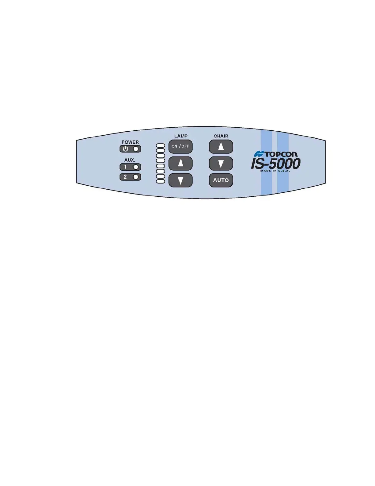
Each of the control panel buttons performs a specific function. Refer to Figures 4.1 for the
locations of the buttons on the control panel.
4.1 Main Power Switch
The main power switch button controls the power to the system and is located on the control
panel. Press on the power button to switch to ON prior to performing any examinations.
A green LED, located next to it, will light to indicate that the system power is ON.
Figure 4.1: Control Panel
4.2 Lamp Switch
The LAMP power and dimmer switch controls the power and light intensity to the overhead
lamp. Press ON/OFF to switch the overhead lamp ON or OFF. This switch has to be in the
ON position to control the overhead lamp using the dimmer. To adjust brightness of the
lamp, simply press the ▲ or ▼ (UP or DOWN) button under LAMP.
4.3 Chair-Control Switch
The exam chair height can be controlled from the control panel. Press the ▲ or ▼ (UP or
DOWN) button on the control panel to adjust the chair to the desired height.
4.4 Chair Auto-Return Button
Pressing the AUTO button on the control panel will return the chair lift to its lowest position.
4.5 Auxiliary Receptacle Button
The auxiliary buttons, AUX 1 & 2, control the power to the auxiliary receptacles located to
the right of the circuit board assembly inside the IS-5000. These receptacles are
recommended for chart projector or any other desired equipment connections.
4.6 Charging Wells
Three (3) smart Charging Wells are available to recharge handheld instrument batteries. It
will perform fast charge if inserted instrument handle is low in charge level. Once handle is
fully charged, charging well will turn to trickle mode to maintain charge level. Normally the
handhelds will maintain full charge if placed in the well during the day. A well is charging if
the green LED is lit. Well charging will not stop even if the main power switch is turned
OFF. It will stop if the stand is unplugged from power.