3 2031005555 Revision B, 04/14
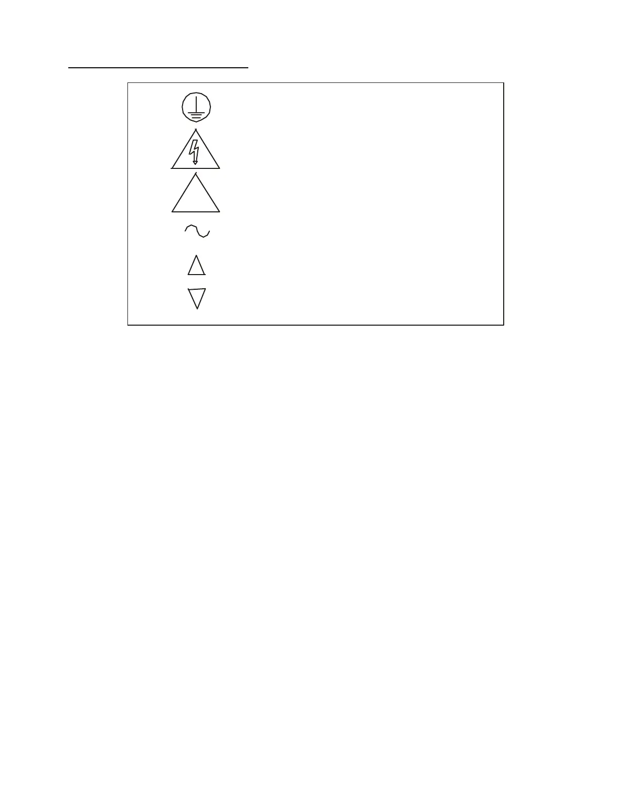
Symbols used on the IS-5000 stand
3. ASSEMBLY
3.1 Tools
The following tools are required to assemble the Topcon IS-5000 Instrument Stand:
1. #2 Phillips screwdriver (for removing shroud cover).
2. Hex wrench sizes 3/16, 5/32, 1/8, 3/32 (included in accessory kit).
3.2 Instrument Stand
1. Unpack the IS-5000 and allow the unit to come to room temperature. The standard
components of the Instrument Stand are as follows: base unit, pole, refractor arm,
and accessory box.
2. Move the IS-5000 stand to desired location using a hand truck. Utilize the plastic
post tubing to position stand (Do not move or position stand by gripping or pulling
on the shroud cover or the plastic front cover). Use protective padding if needed.
3. Unscrew the seven (7) Phillips screws from the shroud cover of the IS-5000, and
then carefully remove the cover.
4. Back out the two (2) set screws from the black, steel tube bracket, and remove the
plastic tubing out of the bracket. Insert pole into the steel tube bracket, and slide it
down until it stops. Rotate the pole until it drops into the keyed slot.
NOTE: Orient the electrical access holes of the pole towards the rear of the stand.
Tighten the two (2) set screws into the tube securely.
5. Level the CS-5 by making sure the pole is vertical in two directions. If the pole is
not level, shim the underside of the CS-5 floorplate as required so that it is level.
Protective Earth ground location
CAUTION: Electrical shock possibility
!
ATTENTION: Information provided in manual
Alternating Current Symbol
UP Symbol
DOWN Symbol