klx
5) Il sensore sole o luminosità si attiva con il “Dip-switch” N.6 che deve essere in
posizione OFF;
6) Il sensore luminosità (sole) interviene ogni qualvolta il valore d'intensità luminosa
oltrepassa la soglia programmata e vi permanga per almeno 10 minuti consecutivi.
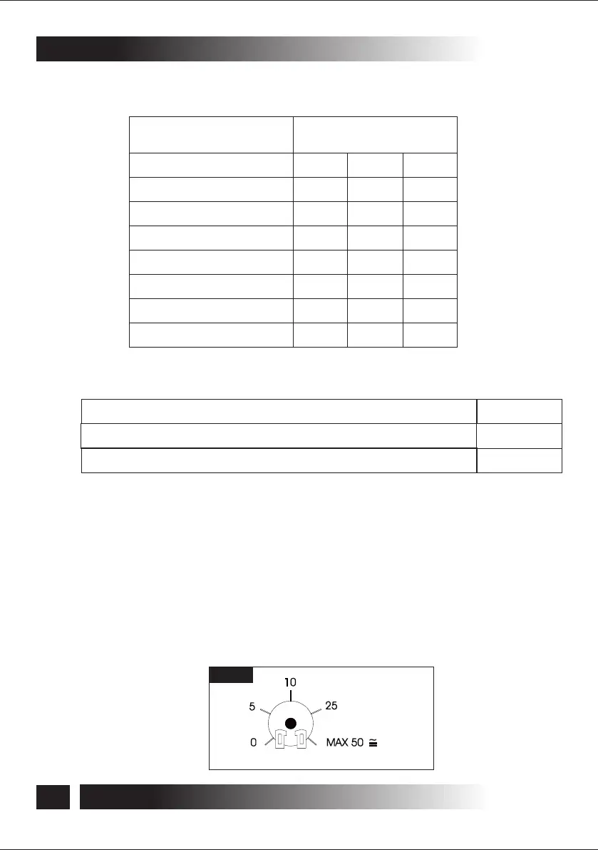
La soglia d'intervento si regola agendo sul Trimmer RT1 (Fig.3) posto nella scheda
elettronica della centralina. Il Trimmer regola da 0 (buio) a circa 50 klx (sole brillante e
cielo sereno di mezzogiorno), con valori intermedi progressivi; (vedi schema riportato
sotto). Il superamento della soglia impostata sul Trimmer, genera un comando
APRE/CHIUDE ai motori collegati alle uscite M5, M6 (motori N.3 e N.4).
Sensore luminosità abilitato (sensori Vento/Pioggia uscite M5-M6 disabilitati)
Sensore luminosità disabilitato (sensori Vento/Pioggia uscite M5-M6 abilitati)
Tab.2
Tab.3
Velocità
Funzione
5 km/h - (2,083 Hz)
10 km/h - (4,167 Hz)
15 km/h - (6,250 Hz)
20 km/h - (8,333 Hz)
25 km/h - (10,417 Hz)
30 km/h - (12,500 Hz)
35 km/h - (14,583 Hz)
40 km/h - (16,667 Hz)
Dip-switch
N.1 N.2 N.3
OFF OFFOFF
OFF OFFON
ON OFFOFF
ON OFFON
OFF ONOFF
OFF ONON
ON ONOFF
ON ONON
Dip-sw. N.6
OFF
ON
15
ISTRUZIONI PER L'INSTALLAZIONE E L’USO
5- INSTALLAZIONE
TF24R/44R
Fig.3
Nota: con il luminosità abilitato, le uscite M5 e M6 non vengono attivate dal comando di
chiusura o apertura generale.
I codici di programmazione sono riportati in Tab.2: