3
PLACING THE TOOL IN SERVICE
SETTING THE TORQUE
After determining the desired torque, use the torque conversion charts on pages 7 to 20 to determine
the pressure that is necessary to achieve that torque.
1. Connect the tool to the power supply and turn the pump on.
2. Depress the remote control button causing the pressure to be shown on the gauge.
3. Adjust the pressure by loosening the wing nut that locks the pressure adjustment thumbscrew.
Rotate the thumbscrew clockwise to increase the pressure and counterclockwise to decrease the
pressure. When decreasing pressure, always lower the pressure below the desired point and then
bring the gauge back up to the desired pressure.
4. When the desired pressure is reached, retighten the wing nut and cycle the tool again to conrm
that the desired pressure setting has been obtained.
OPERATING THE WRENCH
The position of the tool relative to the nut determines whether the action will tighten or loosen the
nut. (Refer to Dwg. 2 for application
examples). The power stroke of the
piston assembly will always turn the
ratchet hex toward the shroud.
1. Place the ratchet hex on the nut. Make
certain it is the correct size for the nut
and that it fully engages the nut.
2. Position the reaction surface against
an adjacent nut, ange or solid system
component. Make certain that there is
clearance for the hoses, swivels, and
inlets. DO NOT allow the tool to react
against the hoses, swivels, or inlets.
Wrench Positions Dwg. 2
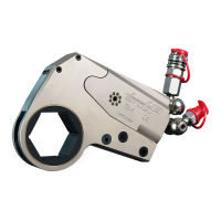
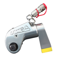
CONNECTING THE TOOL
1. Attach the twin line hose to the
swivel inlets of the square drive
torque wrench using the spring–
loaded quick connect ends.
2. Connect the opposite ends of the
hose to the pump in the same
manner.
3. Push the link retaining pin out of
the low prole drive cylinder.
4. Mate the selected ratchet link to
the cylinder by inserting the end
of the cylinder opposite the swivel
inlets between the side plates of
the ratchet link. (Refer to Dwg. 1)
5. Align the holes for the link retaining
pin and insert the pin through the side plates and cylinder to keep the units joined together.
Dwg. 1