38
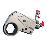
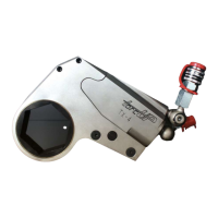
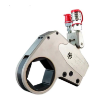
ASSEMBLY OF TX-16, TX-32 AND TX-45 CYLINDER ASSEMBLIES
1. Press the slider pin (14) into one of the sliders (6) until ush with one side. Install the pin through
the hole in the piston rod (2A) and press the remaining slider into the pin.
2. Clamp the housing in copper-covered or leather-covered vise jaws with the inlet end downward.
3. Apply a non-permanent thread-locking compound to the threads of the cylinder gland (20). Use the
gland removal tool (41) to thread the gland into the small central opening in the housing and tighten
until ush with the housing (1).
4. Insert the piston rod (2A), threaded end leading, into the small cylinder gland in the housing. The
notch in the trailing end of the rod should be towards the retaining pin lug.
5. Reclamp the housing so that the inlet end is upwards.
6. Insert the piston cap (2B), hex end trailing, into the bore of the housing and use a socket to thread
and tighten the piston cap onto the piston rod.
7. Thread the end cap (7), O-ring leading, into the bore of the housing and tighten with a socket.
8. Wrap the threads of the swivel assemblies (27) with Teon tape.
9. Install the male coupler swivel into the end cap port and the female coupler into the housing port.
MAINTENANCE SECTION
Inspect all parts prior to assembly. Replace any worn or damaged parts.
ASSEMBLY OF THE RATCHET LINK
1. If the side plate sleeves (12) were removed, press new sleeves, shoulder end trailing, into the right
and left side plates (1 & 2) from the inner face of the side plates. Make certain the sleeves are
square with the side plate faces and that the shoulder of the sleeves enters the recesses in the side
plates and are pressed ush with the faces.
2. For Series TX-2, TX-4, and TX-8 models: Position the upper spacer (8) against the inside face
of the right side plate. Apply a non-permanent thread-locking compound to the threads of the two
upper spacer screws (15) and secure the spacer with the screws through the side plate. For Series
TX-16, TX-32, TX-45 models: Press the spacer roll pin (19) into the right side plate with one end of
the pin ush with the external face of the side plate. Insert the tab of the upper spacer (8) into the
slot in the middle spacer (9). After aligning the holes in both pieces, install them on the spacer roll
pin (19). When they are correctly positioned, apply a non-permanent thread-locking compound to
the threads of the two upper spacer screws (15) and secure the spacers with the screws through
the side plate.
3. Insert the two lower spacer pins (11) into the holes in the lower edge of the right side plate. Apply a
non-permanent thread-locking compound to the threads of the lower spacer screws (16) and secure
the pins with the screws through the side plate. Note: The TX-1 ratchet links do not have Upper
Spacers and Lower Spacers.
4. Place the lower spacer (10) over the pins against the side plate. Make certain it is correctly oriented
so that no part of the spacer extends beyond the edge of the side plate. Note: The TX-1 ratchet
links do not have Upper Spacers and Lower Spacers.
5. Insert the drive pin (4) into the small cross-hole and slot in the drive plate (3). Invert the plate
causing the ends of the pin to enter the slot and move the pin to the narrow end.
6. Position the drive pin spring (5) in the drive plate slot with the two non-connected ends between the
drive pin and the large hole in the slot. Position the closed end of the spring on the opposite side of
the pin and then apply pressure on the spring to align the hole through it with the hole in the drive
plate for the drive pin spring roll pin (18). Insert the spring roll pin into the drive plate, through the
spring and into the far wall of the drive plate.
NOTICE
 Loading...