g008420
Figure11
1.Mountingbolts2.Drivemotor
8.Coatthemotorsplineshaftwithcleangrease
andinstallthemotorbyrotatingthemotor
clockwisesothatthemotorangesclearthe
studs.Rotatethemotorcounterclockwiseuntil
theangesencirclethestuds(Figure11).
9.Tightenthemountingbolts(Figure11).
9
MarkingtheOuterGrass
Baskets
NoPartsRequired
Procedure
Toassistinaligningthemachineforsuccessive
cuttingpasses,dothefollowingproceduretotheNo.
2andNo.3cuttingunitbaskets:
1.Measureinapproximately12.7cm(5inches)
fromtheouteredgeofeachbasket.
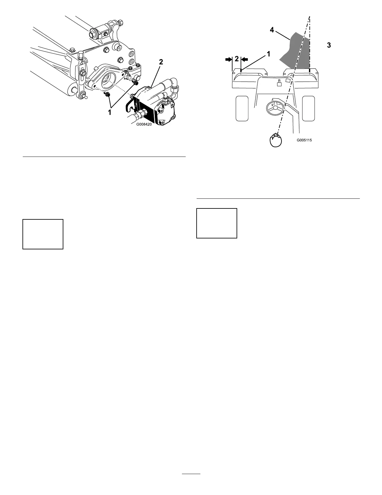
2.Eitherplaceastripofwhitetapeorpaintaline
ontoeachbasketparallelingtheouteredgeof
eachbasket(Figure12).
g005115
Figure12
1.Alignmentstrip
3.Cutgrassonright
2.Approximately12.7cm(5
inches)
4.Keepfocalspot1.8to3
m(6to10ft)aheadofthe
machine.
10
AdjustingtheTransport
Height
NoPartsRequired
Procedure
Checkthetransportheight(Figure14andFigure15)
andadjustitifrequired.
1.Parkthemachineonalevelsurface.
2.Oncuttingunitsequippedwithaoffsetlifthook
(Figure13inset),verifythatthedistancefrom
thetopofthecarrierframeadjustingscrewto
thebackofthecarrierframeis25mm(1inch).
Ifthedistanceisnot25mm(1inch),proceed
tostep4.
15

 Loading...


